39
12345678901234567890123456789012123456789012345678
1
234567890123456789012345678901212345678901234567
234567890123456789012345678901212345678901234567
234567890123456789012345678901212345678901234567
234567890123456789012345678901212345678901234567
234567890123456789012345678901212345678901234567
8
12345678901234567890123456789012123456789012345678
12345678901234567890123456789012123456789012345678
1
234567890123456789012345678901212345678901234567
234567890123456789012345678901212345678901234567
234567890123456789012345678901212345678901234567
234567890123456789012345678901212345678901234567
234567890123456789012345678901212345678901234567
8
12345678901234567890123456789012123456789012345678
PRO FARMER TRIPLEXPRO FARMER TRIPLEX
PRO FARMER TRIPLEXPRO FARMER TRIPLEX
PRO FARMER TRIPLEX
PRO FARMER / TS • GENIUSPRO FARMER / TS • GENIUS
PRO FARMER / TS • GENIUSPRO FARMER / TS • GENIUS
PRO FARMER / TS • GENIUS
STANDARD FOXSTANDARD FOX
STANDARD FOXSTANDARD FOX
STANDARD FOX
USO E MANUTENZIONE USO E MANUTENZIONE
USO E MANUTENZIONE USO E MANUTENZIONE
USO E MANUTENZIONE
OPERATING AND SERVICEOPERATING AND SERVICE
OPERATING AND SERVICEOPERATING AND SERVICE
OPERATING AND SERVICE
Rev. 02
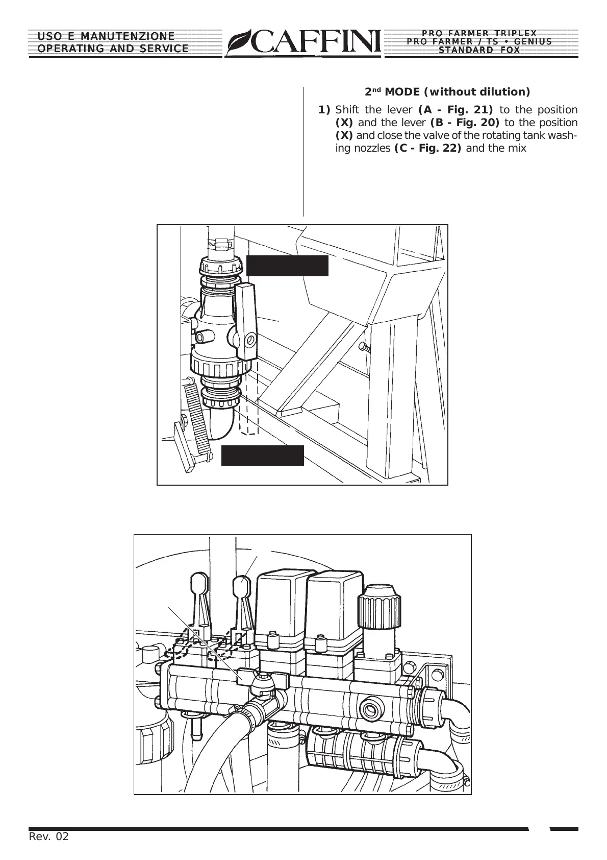
2
nd
MODE (without dilution)
1) Shift the lever (A - Fig. 21) to the position
(X) and the lever (B - Fig. 20) to the position
(X) and close the valve of the rotating tank wash-
ing nozzles (C - Fig. 22) and the mixer (D).
2) Let the P.T.O. run reducing the pressure to
4÷5 Bar about. If the sprayer is fitted with a
MANUAL control unit, move the main pressure
lever and the boom section valves to the ON
position. In case of
ELECTRIC control unit,
move the main push-
button and the boom
section control push-
buttons to the ON
position and then
proceed.
A
Pos. X
Pos. Y
Fig. 21
Fig. 22
2° SISTEMA (senza diluizione)
1) Portare la leva (A - Fig.21) in posizione (X)
e la leva (B - Fig.20) in posizione (X) e chiu-
dere la valvola dei getti rotativi lavacisterna
(C - Fig.22) e del miscelatore (D).
2) Far girare la presa di forza, regolando la pres-
sione a circa 4÷5 Bar. Nel caso di gruppo
comando MANUALE, portare la leva generale
di pressione e le valvole di sezione della barra
in posizione ON.
Nel caso di gruppo
comando ELETTRI-
CO portare il tasto
generale e i pulsanti
di comando sezione
barra in posizione
ON.
D
C