EasyManua.ls Logo

CalAmp LMU-5541

Default Icon
29 pages
To Next Page IconTo Next Page
Loading...
9/28/23, 4:30 PM
LMU-5541 Hardware & Installation Guide - PULS Wiki
https://puls.calamp.com/wiki/LMU-5541_Hardware_%26_Installation_Guide
1/29
Contents
1 Introduction
1.1 About This Manual
1.2 About The Reader
1.3 About CalAmp
1.4 About the CalAmp Location Messaging Unit-LMU-5541™
2 System Overview
2.1 Overview
2.2 Component Descriptions
2.2.1 Wireless Data Network
2.2.2 LMU-5541™
2.2.3 LM Direct™ Server
2.2.4 Backend Software
2.2.5 PULS™
2.2.6 LMU Manager™
3 Hardware Overview
3.1 Location Messaging Unit-LMU-5541™
3.1.1 LMU-5541™ Handling Precautions
3.1.2 Battery Back-up devices
3.1.3 Environmental Specifications
4 LMU-5541™Connectors
4.1 Power Connector
4.2 I/O Connector
4.3 Serial Interface Connectors
4.4 Serial Interface Cables & Accessories
4.5 Accessories
4.6 RF Connector
4.7 I/O Descriptions
4.7.1 Ignition and Inputs
4.7.2 Open Collector Outputs
4.7.3 LED Outputs
4.7.4 Status LEDs
5 Configuration and Activation
5.1 Quick Start - General Config
5.2 Auto provisioning of APNs in LMU
5.3 Activating LMU using AT Commands
6 Installing the LMU
6.1 Preparing for Installation
6.2 Plan the Installation
6.2.1 Size and Placement of the LMU Unit
6.2.2 Placement of Antennas
6.2.3 Access to the SIM (Subscriber Identity Module) Card
6.2.4 Protection from Heat
6.2.5 Visibility of Diagnostic LEDs
6.2.6 Cable Length
6.2.7 Moisture and Weather Protection
6.2.8 Preventing Accidental or Unauthorized Modification
6.3 Installing the LMU in the Vehicle
6.3.1 Place the LMU in the Vehicle
6.3.2 Connect Power, Ignition, and Ground
6.3.3 Place the GPS Antenna
6.3.4 Mount the Comm. Antenna
6.3.5 Typical Connection Sequence
6.4 Installation Verification
6.4.1 Comm Verification
6.4.2 GPS Verification
6.4.3 Inbound Verification
6.4.4 Verification via SMS
7 LMU-LMU5541 Router Configuration & Management
7.1 Configure Maintenance Computer
7.2 Connect to the router
7.3 LuCI
7.4 How to turn on WIFI
7.5 How to test WIFI connectivity
7.6 LED Behavior
7.7 Toggle between Access Point and Client Mode
7.8 Supported and Tested Wi-Fi Related Parameters
8 Firmware & Co-Processor Update
8.1 Requirements
8.2 Preparation
8.3 Maintenance computer network setup
8.4 Programming the IMX processor
8.5 USB driver installation
8.6 Firmware update
8.7 Programming the co-processor
LMU-5541 Hardware & Installation Guide
LMU-5541™
Hardware and Installation Guide
IMPORTANT: DO NOT INSTALL OR USE THE SOFTWARE OR
DOCUMENTATION UNTIL YOU HAVE READ AND AGREED TO
THE LICENSE AGREEMENT AND REVIEWED THE LIMITED
WARRANTY AND REGULATORY INFORMATION.
1 Introduction
Welcome to the LMU-5541™ Hardware and Installation Guide. This manual is intended
to give you information on the basic setup and installation of the CalAmp LMU-5541™
product(s) including hardware descriptions, environmental specifications, wireless
network overviews and device installation.
1.1 About This Manual
The LMU-5541™ is one of the most flexible economy mobile tracking hardware
products available. In order to accurately describe the functionality of these units
we have broken this manual into the following sections:
System OverviewA basic description of a CalAmp LMU-5541™
based tracking system. This includes a description of roles and
responsibilities of each of the CalAmp components as well as a brief
overview of the wireless data technologies used by the LMU-5541™.
Hardware Overview – Describes the physical characteristics and
interfaces of the LMU-5541™.
Installation and Verification – Provides guidance for the installation
of the LMU-5541™ in a vehicle and instructions on how to verify the
installation is performing adequately.
1.2 About The Reader
In order to limit the size and scope of this manual, the following assumptions have
been made about the reader.
You are familiar with GPS concepts and terminology
You have some experience with installing equipment in vehicles
You are familiar with the use of AT Commands
You are familiar with the use of terminal programs such as
HyperTerminal or PuTTY
1.3 About CalAmp
CalAmp is a leading provider of wireless communications products that enable
anytime/anywhere access to critical information, data and entertainment content.
With comprehensive capabilities ranging from product design and development
through volume production, CalAmp delivers cost-effective high quality solutions
to a broad array of customers and end markets. The Company also provides
wireless data communication solutions for the telemetry and asset tracking
markets, private wireless networks, public safety communications and critical
infrastructure and process control applications. For additional information, please
visit the Company’s website at www.calamp.com.

Table of Contents

Other manuals for CalAmp LMU-5541

Question and Answer IconNeed help?

Do you have a question about the CalAmp LMU-5541 and is the answer not in the manual?

CalAmp LMU-5541 Specifications

General IconGeneral
BrandCalAmp
ModelLMU-5541
CategoryGPS
LanguageEnglish

Summary

1 Introduction

1.1 About This Manual

Details the manual's sections and purpose for LMU-5541TM hardware and installation.

1.2 About The Reader

Outlines assumptions about the reader's technical familiarity for using the LMU-5541TM guide.

1.3 About CalAmp

Provides background on CalAmp as a provider of wireless communication products for various markets.

1.4 CalAmp Location Messaging Unit-LMU-5541 TM

2 System Overview

2.1 Overview

Explains the purpose of fleet management systems and the LMU-5541TM's role in delivering location data.

2.2 Component Descriptions

Details the various components that constitute a typical CalAmp fleet management system.

3 Hardware Overview

3.1 LMU-5541 TM Handling Precautions

Covers essential precautions for handling the LMU-5541TM, focusing on Electrostatic Discharge (ESD) risks.

3.1.2 Battery Back-up Devices

3.1.3 Environmental Specifications

Environmental & Performance Specifications

4 LMU-5541 TM Connectors

4.1 Power Connector

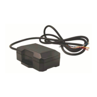
Details the pinout and specifications of the LMU-5541TM's 4-pin Molex power connector for installation.

LMU-5541 TM Connector Overview

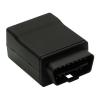
Lists the various connectors available on the LMU-5541TM unit for accessing its capabilities.

4.2 IO Connector

4.3 Serial Interface Connectors

4.4 Serial Interface Cables & Accessories

4.5 Accessories

4.6 RF Connector

4.7 IO Descriptions

Digital Inputs

Lists and describes the various digital input types available on the LMU-5541TM, including Ignition Sense.

Analog to Digital Inputs

Lists and describes the analog-to-digital input channels on the LMU-5541TM for monitoring various signals.

Outputs

Lists and describes the output types available on the LMU-5541TM, such as relay drivers and LED drivers.

iButton 1 Bit Bus

4.7.1 Ignition and Inputs

4.7.2 Open Collector Outputs

4.7.3 LED Outputs

4.7.4 Status LEDs

5 Configuration and Activation

5.1 Quick Start - General Config

Guides users through initial LMU-5541TM configuration to point to the LM DirectTM server via AT commands.

LED #4 GPS LED Definitions

LED #5 Comm LED Definitions

5.2 Auto provisioning of APNs in LMU

5.3 Activating LMU using AT Commands

6 Installing the LMU

6.1 Preparing for Installation

Lists necessary LMU components and preparations required before starting the vehicle installation process.

6.2 Plan the Installation

6.2.1 Size and Placement of the LMU Unit

Provides guidance on selecting an LMU installation location considering dimensions and vehicle fit.

6.2.2 Placement of Antennas

Discusses optimal placement strategies for Comm and GPS antennas to ensure performance and compliance.

Comm Antenna Placement Guidelines

Provides guidelines for positioning the communication antenna for FCC compliance and optimal signal reception.

GPS Antenna Placement Guidelines

Offers advice on GPS antenna placement to maximize signal reception and avoid obstructions.

Installation Planning Considerations

6.3 Installing the LMU in the Vehicle

6.3.1 Place the LMU in the Vehicle

Provides guidance on selecting a suitable physical location for the LMU unit within a vehicle.

6.3.2 Connect Power, Ignition, and Ground

Details the correct wiring procedure for connecting the LMU's power, ignition, and ground lines.

6.3.3 Place the GPS Antenna

Offers instructions for mounting the GPS antenna to ensure optimal sky view and signal reception.

6.3.4 Mount the Comm. Antenna

Provides guidelines for mounting the communication antenna, considering placement relative to GPS and FCC limits.

6.3.5 Typical Connection Sequence

Outlines the sequential steps for connecting LMU components, peripherals, and power during installation.

6.4 Installation Verification

6.4.1 Comm Verification

Details methods to verify cellular network registration and data session using LEDs or AT commands.

6.4.2 GPS Verification

Explains how to verify GPS receiver functionality using the status LED or AT commands.

6.4.3 Inbound Verification

6.4.4 Verification via SMS

7 LMU-LMU5541 Router Configuration & Management

7.1 Configure Maintenance Computer

Guides on configuring the maintenance computer's IP settings to match the LMU-LMU5541TM subnet.

7.2 Connect to the Router

Instructs on accessing the LMU's LuCI interface via a web browser by entering its IP address.

7.3 LuCI Login Process

Details the login process for the LuCI web interface, requiring specific username and password credentials.

7.4 Enable Wi-Fi Interface

7.5 Test Wi-Fi Connectivity

7.6 LED Behavior Overview

7.7 Toggle Wi-Fi Mode

7.8 Supported Wi-Fi Parameters

8 Firmware & Co-Processor Update

8.1 Requirements for Update

Lists necessary hardware, software, and files for performing LMU firmware and co-processor updates.

8.2 Preparation for Update

Outlines preparation steps on the maintenance computer and required connections for firmware updates.

8.3 Maintenance Computer Network Setup

8.4 Programming the IMX Processor

8.5 USB Driver Installation

8.6 Firmware Update Procedure

8.7 Programming the Co-processor

8.8 Final Steps After Update

Related product manuals