40
1002595 ISSUE 5 M172 VARIHEAT
VARIHEAT AA SYSTEM OWNER INSTALLATION MANUAL
Electrical safety
It is important to ensure at all aspects of e installation comply wi e
latest I.E.T. Regulations. It is also important to ensure at any remote devices
which terminate wiin e pool hall are of e type and voltage as specified in
e I.E.T. Regulations latest edition.
The machine should be installed in accordance wi EMC2004/108/EC.
Protected supply
Whilst not mandatory, e Danerm Group recommend at an R.C.C.B. is
always fitted or at e supply is to local electricity auority recommendations,
and at all ducting is bonded in accordance wi ese regulations.
The supply to e machine should incorporate fuses or motor rated circuit
breakers (Type C) to specified rating, (See section 5.0 DATA SHEET on page
54.) H.R.C. fuses are recommended. An isolator must be fitted wiin clear
view and not more an 2 metres away. The isolator must have a minimum
3mm air gap in e off position.
All units must be correctly eared/grounded. An ear leakage trip is
recommended to be fitted to all pool electrics.
Inconsistent electrical supply
The following limits of operation must not be exceeded if Calorex machines are
to be guaranteed eier in performance or warranty terms:
Voltage Minimum Maximum
Single phase machines 207V 253V
Three phase machines 360V 440V
Frequency 47.5Hz 52.5Hz
Note: The voltage must be measured at e heat pump mains terminals wi
all e fans/compressors running at e rated load condition.
Correct cable sizing
The cable supplying electricity to a machine wi a given load must increase
in cross sectional area (C.S.A) as e leng increases in order at e voltage
drop wiin e cable does not exceed recommended limits. Cable sizing
should be calculated by an approved electrician wi due consideration
to I.E.E and local codes of practice.
Note: Three phase Variheat models 1200 and 1500, are fitted wi phase
protection and will not run if phases are connected incorrectly.
Warning: The red lamp adjacent to e control panel indicates at e Variheat
is live. It is necessary to wait ree minutes aer e supply is disconnected
before removing any panels or commencing servicing of e Variheat.
3.5 ELECTRICAL INSTALLATION
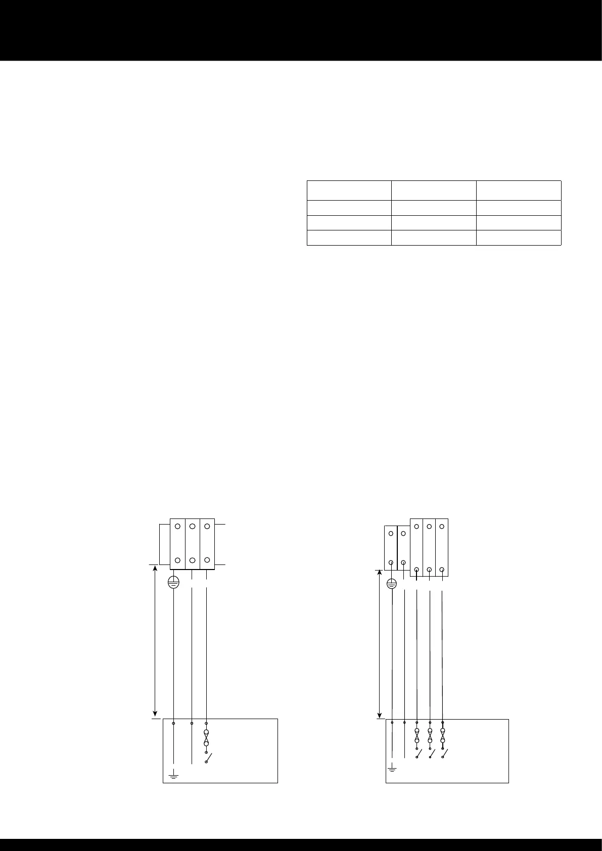
Power supply terminal block layout
single phase
N
L
L
2
3
N
1
4
5
L1 L2 L3
3
N
1/L1 3/L2 5/L3
21
Switched fuse
isolator
see data sheet
for ratings
Power supply terminal block layout
ree phase
N L1
L3
L2
Switched fuse
isolator
see data sheet
for ratings
Switched fuse
isolator to be
wiin 2m (6 feet)
and wiin sight
of front of unit
Switched fuse
isolator to be
wiin 2m (6 feet)
and wiin sight
of front of unit