39
1002595 ISSUE 5 M172 VARIHEAT
3.4 ELECTRICAL CONNECTIONS
There are 3 cable glands in e electric box tray and two furer knock-outs.
Use e le hole for access to e power terminals. Use oer available access
points for e optional interface terminals.
All terminals are accessible by removing e electric box cover.
The touchscreen can be moved from e default location to e alternative
position if is is more convenient for e user to access.
Wi e power isolated and e black cover removed, e screen rear can be
removed by pressing e button on top. The screen can be unscrewed and
moved to e alternative location or rotated by 180°. To rotate by 90°, remove
e locating pin and ensure e screen is securely fixed to prevent rotation.
Once e touchscreen is positioned, reattach e rear module.
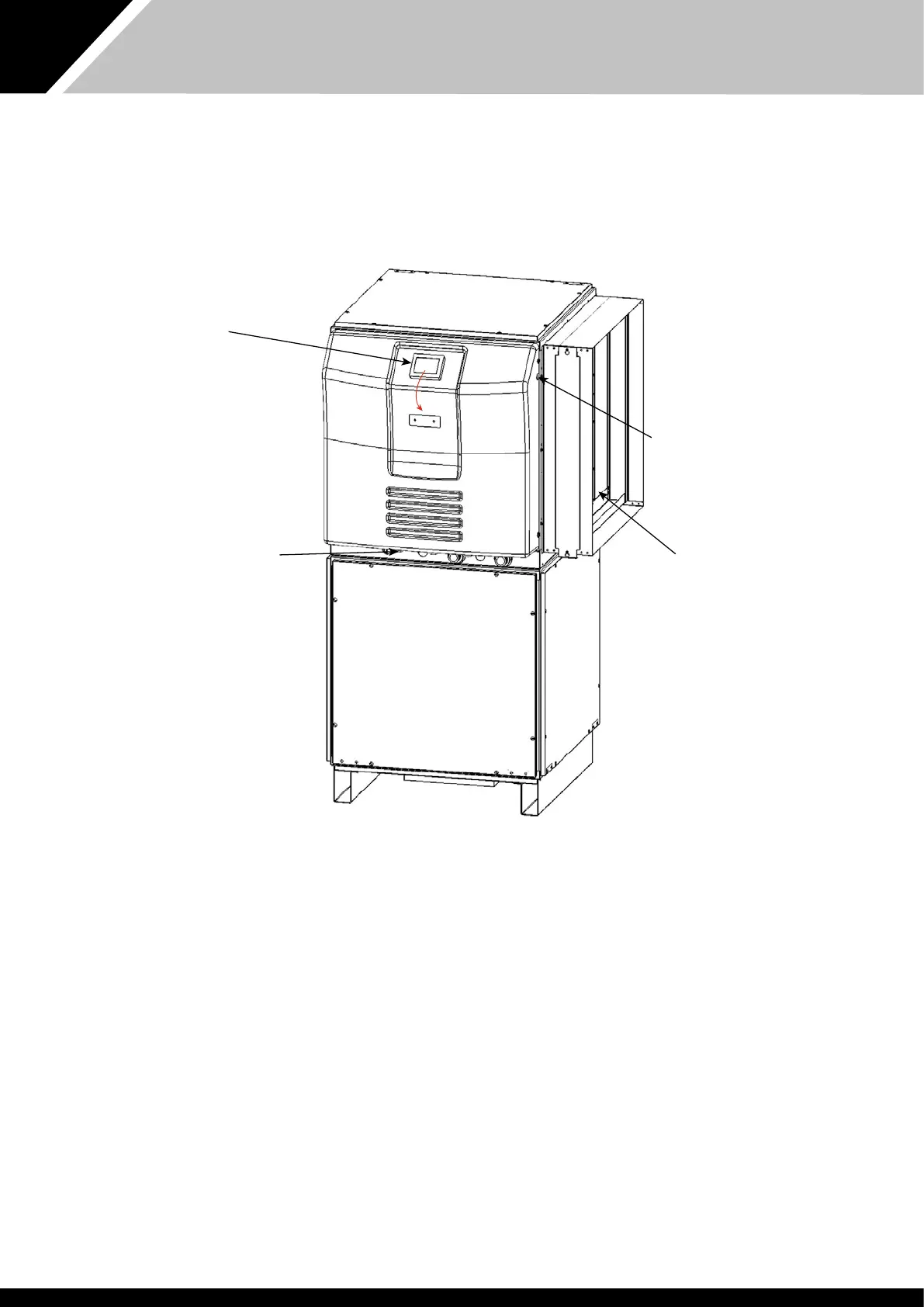
Power light
Refrigeration module
Fan module
Cable entry points
Touchscreen user
interface.
The touchscreen can
easily be moved to e
front face of e electric
box cover.