5 OPTIONS
ENTER-Switch
CAI LED
USER MANUAL
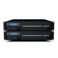
VORTEX 3 QUADRO
P.24
USER MANUAL
VORTEX 3 QUADRO
P.25
5.1 CAI (CAMCO Audio Interface)
CAI is a bus system, in which all signicant device functions can be monitored
externally and remotely controlled using a master PC. Up to 99 devices can be
controlled in parallel in each phase of the bus system, which simply consists of
a two-core insulated cable. The master can serve several phases for larger appli
-
cations. For more information, please contact your dealer or distributor.
CAI allows:
To control the output-level of each Channel independently
(exception: mono modes, only Channel A(C) is affected)
To mute each channel independently
(exception: mono modes, only Channel A(C) is affected)
To switch the
VORTEX
into STANDBY (and back again)
To monitor temperature, output-signal, clip, output-current.
5.1.1 Wiring
To connect the
VORTEX
to your CAI system use a fully-wired telephone-type
cable with RJ12 connectors. For longer distances use high grade cable like
for RS485, DMX512 for AES/EBU digital audio. You can chain several
VORTEX
ampliers using the second CAI connector on each amplier. A linear network
topology is recommended with 100 Ohm termination at its end. Please refer to
RS485 specications.
5.1.2 CAI Address Settings
The VORTEX 3 QUADRO uses two addresses to communicate with the master
PC. You only select the address for amplier A/B, the address of amplier C/D is
automatically set to address for amplier A/B plus one.
The CAI address selection procedure will not affect the operation of the
VORTEX
but whilst this procedure is active, the volume cannot be adjusted by
using the pots.
NOTE: Ensure you return both pots to their original position after address
selection is complete, otherwise the amplier will change its volume level
to the new pot positions!
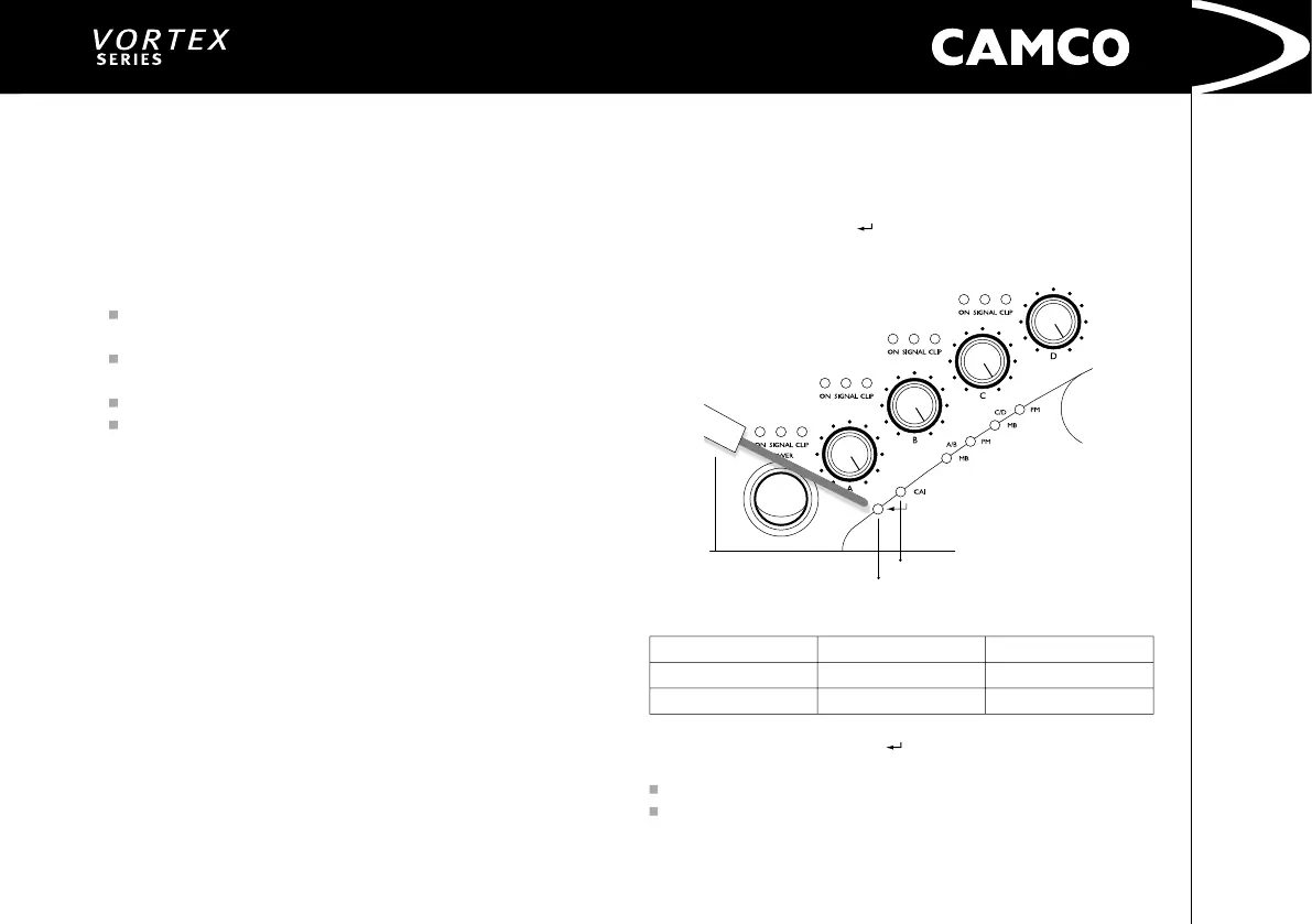
Briey press the ENTER-Switch
. This push button switch can be accessed
through the 3 mm hole in the front panel located between the On/Off switch
and the LEDs.
Example of LED sequences for different address settings:
Adresses (A/B)/(C/D)
On-LED Channel A
=>
Tens
On-LED
Channel B
=> Units
01/02 (factory settings)
0* ash
1* ash then short pause
25/26
2* ashes then short pause
5* ashes then short pause
After briey pressing the Enter-Switch
the actual address of amplifier A/B will be
displayed by the On LEDs of ChA and ChB. The address of amplier C/D is not shown.
Flashing of On LED channel A indicates the tens
Flashing of On LED channel B indicates the units of the address of amplier A/B