Pag. 15 - FA01289M4A - 12/2018 © Came S.p.A.
count, said module and all of the devices associated with
it must be deleted from the account.
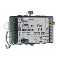
7 Antenna mount.
8 Antenna.
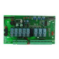
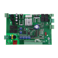
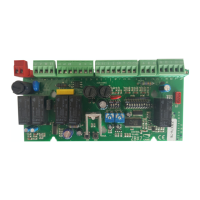
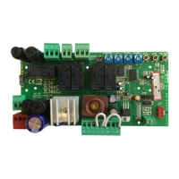
I RSE card, to be inserted in Came control panels.
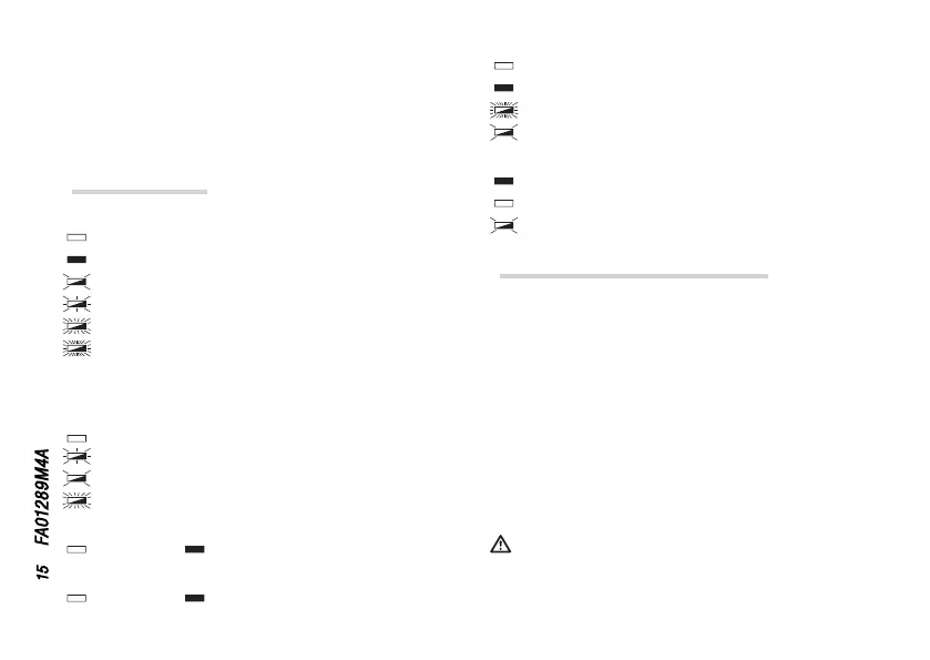
Warning LEDs
LED key
O
On
Flashes every three seconds,
Flashes once per second,
Flashes three times per second,
Flashes five times per second.
Warning key
❶ GSM LED (blue)
GSM Modem O,
Not registered on the GSM network,
Registered on the GSM network,
Active GPRS connection.
❷ OUT1 LED (red)
Relay 1 open, relay 1 closed.
❸ OUT2 LED (red)
Relay 2 open, relay 2 closed.
❹ POWER LED (green)
Module is powered o,
Module powered up and configured/associated,
Module is not configured (only factory settings),
P1 button pressed.
❺ CONN LED (red)
Module connected to CAMEConnect,
Module not connected to CAMEConnect,
Firmware remote update underway.
Description of the terminals
IN1 - COM Input 1 (24V DC max) and common input.
IN2 - COM Input 2 (24V DC max) and common input.
OUT1 Relay 1, 30V DC - 1A (max) N.O.
OUT2 Relay 2, 30V DC - 1A (max) N.O.
GND Interface 485 earth.
B PIN B interface 485.
A PIN A interface 485.
2 – Power supply.
10 + Power supply.
Where the device is connected to a CAME control panel
equipped with CRP via terminal A-B-GND, power the module
only from terminals 2-10 on the panel itself.
 Loading...