Pag. 21 - FA01289M4A - 12/2018 © Came S.p.A.
3 secondes puis le relâcher pour remettre le module en marche.
Tout module réinitialisé aux valeurs d’usine ayant déjà
été enregistré et configuré sur un compte CAMEConnect
devra être éliminé du compte en question avec tous les
dispositifs y étant associés.
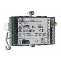
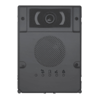
7 Fiche antenne.
8 Antenne.
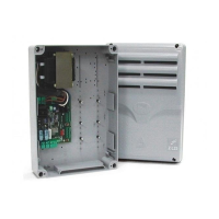
I Carte RSE, à insérer sur les armoires de commande Came.
Voyants de signalisation LED
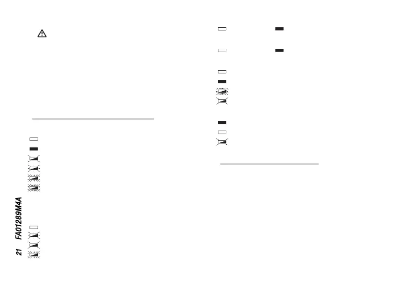
Légende symboles voyants
Éteint
Allumé
Clignote toutes les 3 secondes,
Clignote toutes les secondes,
Clignote 3 fois par seconde,
Clignote 5 fois par seconde.
Signification des signalisations
❶ LED GSM (bleue)
Modem GSM éteint,
Non enregistré au réseau GSM,
Enregistré au réseau GSM,
Connexion GPRS activée.
❷ LED OUT1 (rouge)
Relais 1 ouvert, Relais 1 fermé.
❸ LED OUT2 (rouge)
Relais 2 ouvert, Relais 2 fermé.
❹ LED POWER (verte)
Module hors tension,
Module alimenté et configuré/associé,
Module non configuré (condition d’usine),
Bouton P1 enfoncé.
❺ LED CONN (rouge)
Module connecté à CAMEConnect,
Module non connecté à CAMEConnect,
Mise à jour du firmware en cours à distance.
Description des bornes
IN1 - COM Entrée 1 (24 VDC max.) et commun entrée.
IN2 - COM Entrée 2 (24 VDC max.) et commun entrée.
OUT1 Relais 1, 30 VDC - 1 A (max.) N.O.
OUT2 Relais 2, 30 VDC - 1 A (max.) N.O.
GND Masse interface 485.
B PIN B interface 485.
A PIN A interface 485.
2 – Alimentation.
10 + Alimentation.
 Loading...