BUS
OH/SER
RX+
M2
M1
RX–
TX+
TX–
S
–
+
–
+D
–D
C
I1
I2
I3
–
TX–
TX+
RX–
RX+
LA
M2M1
OH/A.01
M1
M2
LA
LA
M3
BK
VAS/100.30
TS07 - TS10
G
2
+
–
I1
I2
O1
O2
C
1
2
1
A
ETI/Domo
Switch
Port 1
Port 0
+
–
VAS/101
–
+
18V
230V
M1
M2
RX +
LA
SERVICE
RX –
TX +
TX –
–
–
+
S
OH/3RPI
LA
C
I1
I2
I3
TA/P1
LA
C
I1
Page 7 - Manual code: FA00771-EN vers. 1 05/2017 © CAME S.p.A. - The data and information in this manual are to be considered subject to change at any time and without the need for any advance warning.
Page 6 - Manual code: FA00771-EN vers. 1 05/2017 © CAME S.p.A. - The data and information in this manual are to be considered subject to change at any time and without the need for any advance warning.
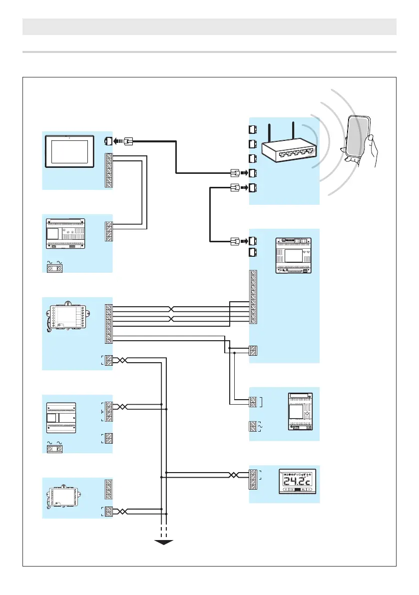
INSTALLATION DIAGRAMS
Installing a terminal in systems without PoE
Where there is no PoE, the terminals must be connected to a local power supply.