LEFM 200 Modbus User Manual IB0147 Rev. 8
December 2010 Page 11 Section 2
Using the above coefficients, the transmitter does a linear scale:
Analog Input (engineering units) = Y1 +(Analog Input-X1)*(Y2-Y1)/(X2-X1)
For example, for a 100 RTD (-100 to 100°C), 0 volts represent -100°C and 5 volts represents
100°C.
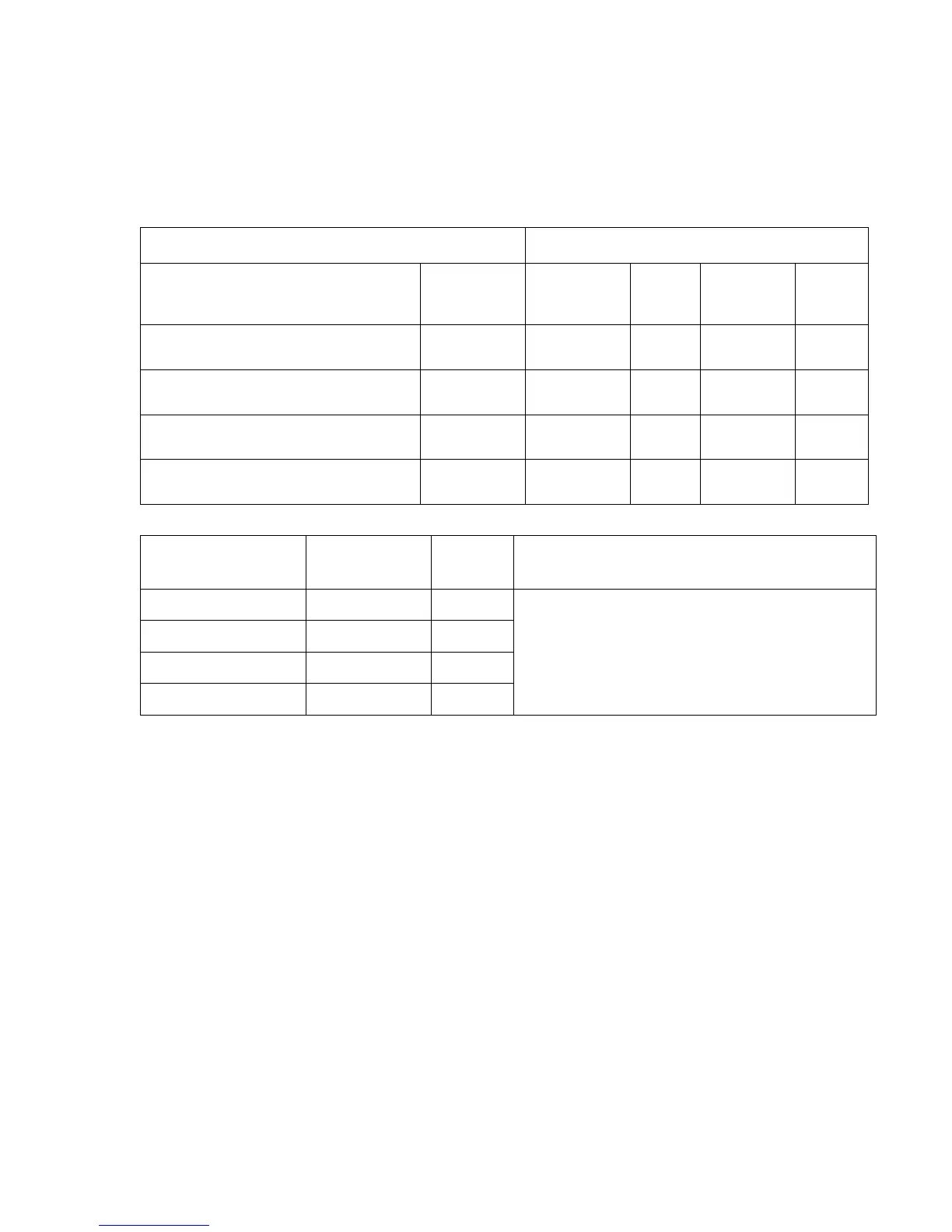
Holding Register Address
Variable Description Name
Meter Body
Temp Input1
Input 2
Input 3*
Density
Input 4*
Minimum Voltage for Inputs X1(j)
104 112 120 128
Minimum Engineering Value at
Minimum Voltage
Y1(j) 106 114 122 130
Maximum Voltage for Inputs X2(j)
108 116 124 132
Maximum Engineering Value at
Maximum Voltage
Y2(j)
110 118 126 134
Setup Variable
Holding Register
Variable
Definition
Address Note
Meter Body Temp Float 1170
Use these registers to override the Analog
Inputs with values from the Flow Computer
or Plant Computer
Fluid Pressure Float 1172
Fluid Temperature Float 1174
Density Float 1176
 Loading...