LEFM 200 Modbus User Manual IB0147 Rev. 8
December 2010 Page 25 Section 4
4.0 DATA OUTPUTS – INPUT REGISTERS
The following table defines the addresses for the Modbus user outputs (for all systems).
Input Registers are accessed from the 200 Series Electronics with Modbus Function Code 4.
4.1 Path Transit and Delta Time Measurements
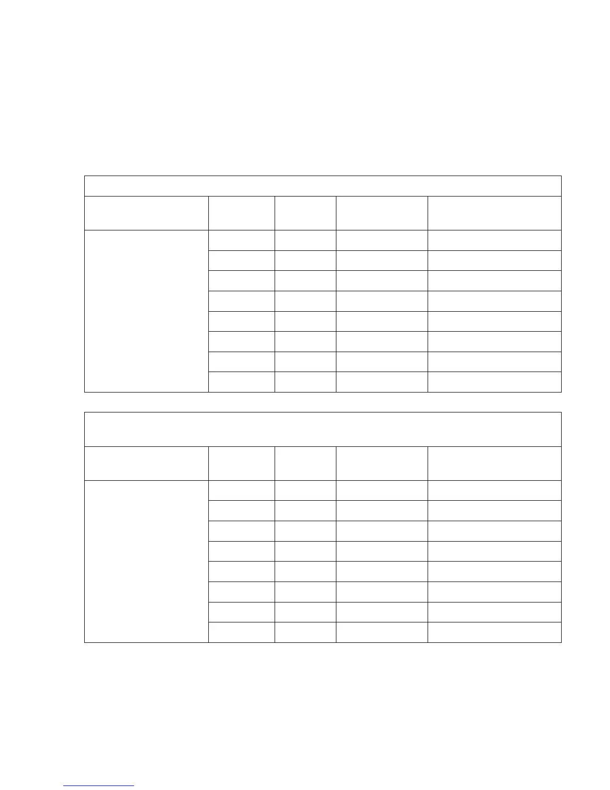
Transit Time Downstream
Output Variable
Input Register
Variable
Definition
Address Units Notes
Float 0 Nanoseconds Path 1
Float 2 Nanoseconds Path 2
Float 4 Nanoseconds Path 3
Float 6 Nanoseconds Path 4
Float 500 Nanoseconds Path 5
Float 502 Nanoseconds Path 6
Float 504 Nanoseconds Path 7
Float 506 Nanoseconds Path 8
Difference in Time of flight upstream to downstream
This term is linear with Velocity and Flow Rate
Output Variable
Input Register
Variable
Definition
Address Units Notes
Float 8 nanoseconds Path 1
Float 10 nanoseconds Path 2
Float 12 nanoseconds Path 3
Float 14 nanoseconds Path 4
Float 508 nanoseconds Path 5
Float 510 nanoseconds Path 6
Float 512 nanoseconds Path 7
Float 514 nanoseconds Path 8
 Loading...


