IB0147 Rev. 08 LEFM 200 Modbus User Manual
Section 2 Page 10 December 2010
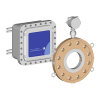
Setup Variable Holding
Register
Variable
Definition
Address* Notes
Password Entry Integer 2000 Enter Password In This
Register
USER0 Integer 2001 Set Password For USER0
USER1 Integer 2002 Set Password For USER1
USER2 Integer 2003 Set Password For USER2
USER3 Integer 2004 Set Password For USER3
USER4 Integer 2005 Set Password For USER4
ADMIN5 Integer 2006 Set Password For ADMIN5
2.9 Analog Inputs
The “Units” Holding Register let’s the user select the units for the input interfaces. Typically,
the meter only has an input from the meter body RTD. However, other engineering units can be
used.
2.9.1 Analog Inputs – Units
Units
The Holding Register (102) scales the units as follows:
The analog inputs are slightly different between the 200C electronics and the 200Ci electronics.
For clarity, these two products are treated separately.
2.9.2 Analog Inputs – 200C Electronics Only
Each analog input is scaled using four parameters as follows:
Input Scaling - X1, Y1, X2, Y2
X1 and X2 are in volts (Min = 0; this is associated with 0 volts. Max = 5). Note: The 4 – 20 mA
input is converted to 0 to 5 volts (as is the RTD input).
Y1 and Y2 are in engineering units. Where:
X1 = Minimum limit voltage
Y1 = Engineering value associated with the minimum voltage
X2 = Maximum limit voltage
Y2 = Engineering value associated with the Maximum voltage
1 1 2 1
Temperature (°F=0, °C=1)
Pressure (psig =0, kg/cm2=1, bar=2, kPa=3)
Density (g/cc=0, kg/m³=1,API=2,lbm/ft³=3)
Velocity (ft/s - in/s=0, m/s=1)
 Loading...