LEFM 200 Modbus User Manual IB0147 Rev. 8
December 2010 Page 13 Section 2
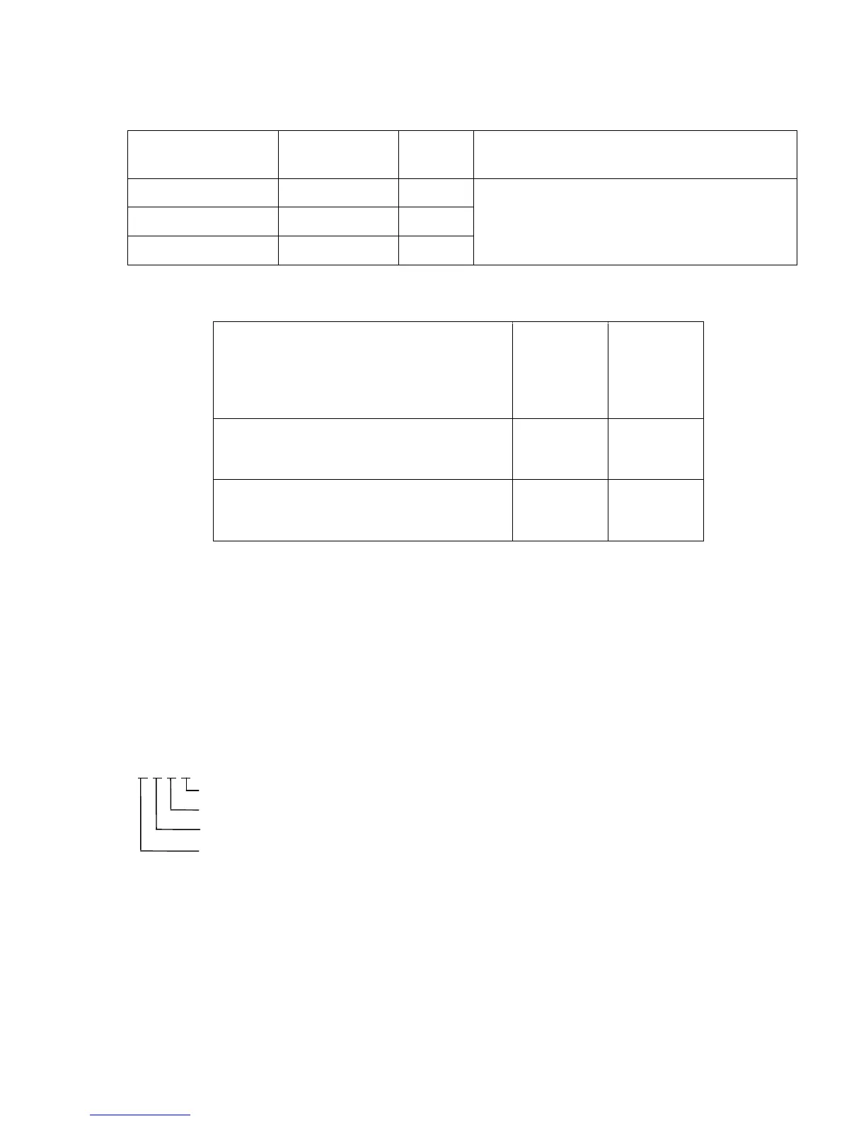
The Modbus registers are located as for the 200C electronics in the following registers.
Setup Variable
Holding Register
Variable
Definition
Address Note
Fluid Pressure Float 1172
Use these registers to input with values from
the Flow Computer or Plant Computer
Fluid Temperature Float 1174
Density Float 1176
Finally, the meter body temperature can be scaled (offset and slope) with the following registers.
Variable Description Name
Holding
Register
Address
(Float)
Temperature Offset -units are same as
defined in Section 2.9.1)
Offset
3328
Temperature Slope (degrees/degrees) -
units are same as defined in Section 2.9.1)
Slope 3330
2.10 Analog Outputs
The “Units” Holding Register let’s the user select the units for the output interfaces.
2.10.1 Analog Outputs – Units
Units
The Holding Register (102) scales the analog outputs as follows:
2.10.2 Analog Outputs – 200C Electronics Only
Output Scaling B1, A1, B2, A2
B1/B2 are in engineering units and A1/A2 are in counts (0 for minimum range, 65535 for
maximum range).
Analog Output (counts) = A1 +(analog engineering units-B1)*(A2-A1)/(B2-B1),
1 1 2 1
Temperature (°F=0, °C=1)
Pressure (psig =0, kg/cm2=1, bar=2, kPa=3)
Density (g/cc=0, kg/m³=1,API=2,lbm/ft³=3)
Velocity (ft/s - in/s=0, m/s=1)