IB0147 Rev. 08 LEFM 200 Modbus User Manual
Section 2 Page 14 December 2010
Default Outputs
Output 1 Flow,
Output 2 VOS (sound velocity),
Output 3 Temperature,
Output 4 Density
The default output units are as follows:
Flow – based on units conversion and time units conversion
VOS (Sound velocity) is units of velocity – in/s or m/s
Temperature is °F or °C
Relative Density in Density Units
The outputs can also be mapped to any Modbus Input Register by putting that register value into
AnalogOutputMap register, 1124 to 1127. The units are then the units of that register and the
scaling must be adjusted accordingly.
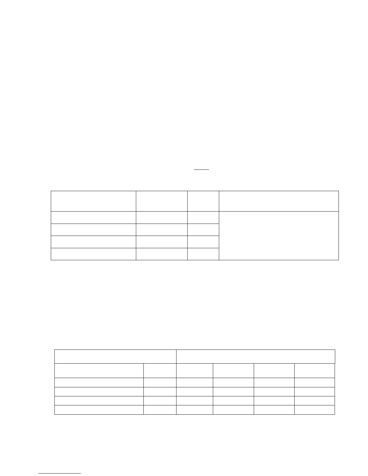
Setup Variable Holding
Register
Variable
Definition
Address Note
AnalogOutputMap1 Integer 1124
0 = Use Default Output Values
Use Modbus Input Register Value to
Output the Value of that Register.
AnalogOutputMap2 Integer 1125
AnalogOutputMap3 Integer 1126
AnalogOutputMap4 Integer 1127
The following table defines addresses for the Analog Output setups. The variables are entered as
Floats, however, the counts values are limited to integers. The equation used is as follows:
Analog Output(i) (counts) = B1 +(Output(i)-A1)*(B2-B1)/(A2-A1)
Where:
65535 is full scale (i.e., 20 mA for a 4-20 mA output)
0 is minimum scale (i.e., 4 mA for a 4-20 mA output)
For Ci Units there is only one (1) analog output and the full scale counts are configured at the
factory.
Holding Register Address
Variable Description Name Output1 Output 2 Output 3 Output 4
Minimum Engineering Value A1(j) 136 144 152 160
Minimum Count Value B1(j) 138 146 154 162
Maximum Engineering Value A2(j) 140 148 156 164
Maximum Count Value B2(j) 142 150 158 166