LEFM 200 Modbus User Manual IB0147 Rev. 8
December 2010 Page 15 Section 2
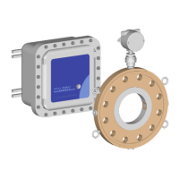
2.10.3 Analog Outputs – 200Ci Electronics Only
Output Number 1- Scaling B1, A1, B2, A2
B1/B2 are engineering units and A1/A2 are Digital to Analog converter counts (0 for minimum
range, 16383 for maximum range).
Analog Output (counts) = A1 + (analog engineering units-B1)*(A2-A1)/(B2-B1),
For Ci Units there is only one (1) analog output and the full scale counts are configured at the
factory. Full scale is approximately 16383, but this value is scaled during manufacturing and
should not be changed. Likewise, the minimum value is scaled during manufacturing and should
not be changed.
Variable Description Name
Holding
Register
Address
Output1
Minimum Engineering Value
A1
(do not
change)
136
Minimum Count Value
B1 138
Maximum Engineering Value
A2
(do not
change)
140
Maximum Count Value
B2 142
Default Outputs
Output 1 Flow,
The default output units are as follows:
Flow – based on units conversion and time units conversion
The output can also be mapped to any Modbus Input Register by putting that register value into
Analog Output Map register, 1124. The units are the units of the register and the scaling must be
adjusted accordingly.
Setup Variable Holding
Register
Variable
Definition
Address Note
AnalogOutputMap1 Integer 1124
0 = Use Default Output Values
Use Modbus Input Register Value to
Output the Value of that Register.