M52 Microprocessor User's Guide
M52UMCT Oct-03 53
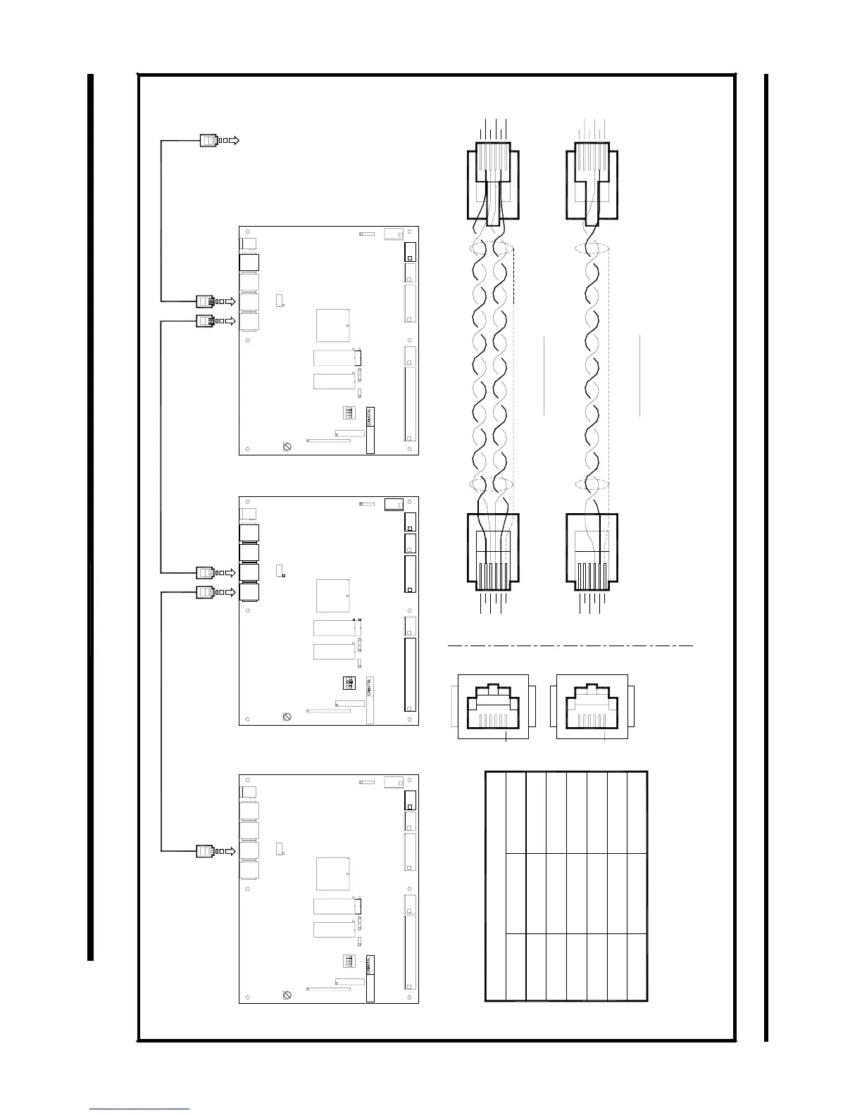
3. Screen for each cable segment must be connected to ground from one end only.
2. Twisted pair cable should be screened and with 24AWG or larger conductor.
1. J21 and J22 are RJ12 socket.
J21 and J22 (RS485)
Not used
Not used
Not used
T/R(-)
T/R(+)
Grd
Half duplex
2
1
4
5
6
3
PIN No.
Note :
R(+)
Grd
Not used
T(+)
T(-)
R(-)
Full duplex
5
3
1
2
4
6
5
3
1
4
2
6
Half duplex
Full duplex
2
4
6
3
1
5
4
3
5
2
1
6
1
M52ES02E
14 June 1999
Electrical Schematic - RS485 Serial Communication Link
SATCHNET, M52 CONTROL SYSTEM
Dimension: Not to scale
CANATAL
RS485 Port
To Host Systems'
1
M52 - M V4
1
J14
J51
1
J13
1
J12
1
VR1
ON
1
LCD1
4
SW1
23
JP1
KB1
JP11JP2
U5 U3
U1
U14
J11
1
J01
BL1
J02
J22 J31 J32J21
1
M52 - M V4
1
J14
J51
1
J13
1
J12
1
VR1
ON
1
LCD1
4
SW1
23
JP1
KB1
JP11JP2
U5 U3
U1
U14
J11
1
J01
BL1
J02
J22 J31 J32J21
Socket
PC Board
J32
1
3
SW1
M52 - M V4
1
21
LCD1
ON
KB1
VR1
J14
J51
1
JP11JP1
4
JP2
U5 U3
1
J13
1
J12
U1
U14
J22J21 J31
1
J11
J01
BL1
J02
1