EasyManuals Logo

C&T PC400 Series User Manual

Default Icon
71 pages
To Next Page IconTo Next Page
To Previous Page IconTo Previous Page
Page #30 background imageLoading...
Page #30 background image
PC400 / PC410 l User’s Manual
30
Chapter 2: Switches and Connectors
30
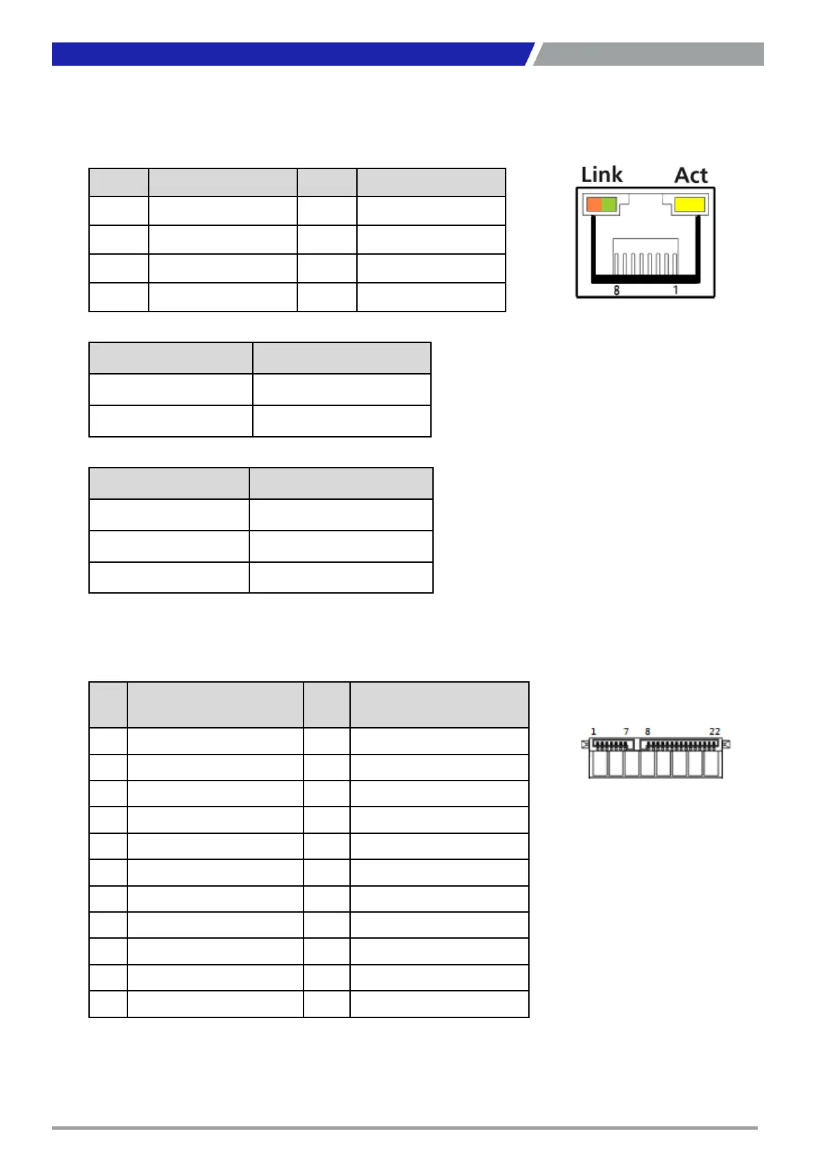
LAN1, LAN2: RJ45 with LEDs Port
Connector Type: RJ45 Connector
Pin Definition Pin Definition
1 LAN_MDI0P 5 LAN_MDI2N
2 LAN_MDI0N 6 LAN_MDI1N
3 LAN_MDI1P 7 LAN_MDI3P
4 LAN_MDI2P 8 LAN_MDI3N
Link LED Status Definition
Steady Orange 1Gbps Network Link
Steady Green 100Mbps Network Link
Off 10Mbps Network Link
Act LED Status Definition
Blinking Yellow Data Activity
Off No Activity
SATA with Power Connector
Pin
SATA1_1 Definition Pin SATA1_1 Definition
1 GND 12 GND
2 TxP 13 GND
3 TxN 14 +5V
4 GND 15 +5V
5 RxN 16 +5V
6 RxP 17 GND
7 GND 18 GND
8 NC 19 GND
9 NC 20 +12V
10 DEVSLP 21 +12V
11 GND 22 +12V

Questions and Answers:

Question and Answer IconNeed help?

Do you have a question about the C&T PC400 Series and is the answer not in the manual?

C&T PC400 Series Specifications

General IconGeneral
BrandC&T
ModelPC400 Series
CategoryControl Unit
LanguageEnglish