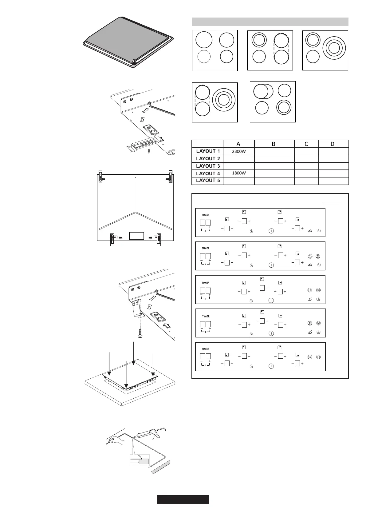
FLUSH INSTALLATION
After checkng that the poston of
the hob s correct fll the gap
between the worktop and the hob
wth slcone adhesve. Flatten the
slcone layer wth a scraper or
wth wet fnger damped wth water
and soap before t forms.
Do not use the hob untl the
slcone layer t s completely dry.
A watertght seal gasket s
suppled wth the hob. Ft
the seal gasket around the
bottom hob as descrbed
and make sure that t s
properly ftted to avod any
leakage nto the supportng
furnture.
Bottom
Normal Fxng:
- Get the fxng clps from accessory bag
and screw them nto the poston shown
on bottom box. (Do not tghten the
screws to block clps, they should move
freely)
- Turn the clps and tghten
them fully.
- Insert the hob n center
poston of cut out.
Get four sprngs form accesory bag and
screw them onto bottom box as shown
n fgure.
Center and nsert the hob.
Press the sdes of hob untl t
s supported around ts
entre permeter.
Quck Fxng: (Dependng on model)
06 GB
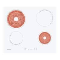
1000+700 W
1000+700 W
1500+900 W
1200 W
1050+900+750 W
1050+900+750 W
1200 W
1200 W
1200 W
1800 W
1200 W
1200 W
1800 W
1000+700 W
-
-
1800 W
1800 W
B
C D
BA
C
B
C
D
A
C
B
B
D
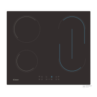
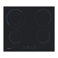
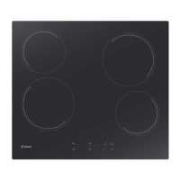
LAYOUT 1 LAYOUT 2 LAYOUT 3
LAYOUT 4 LAYOUT 5
A A
C
A
1
2
3
4
5
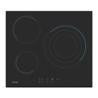
LAYOUT
1. ON/OFF
4. TIMER
6. Cooking zone programming indicator
2. " + "
8. Chld lock
According to model
3. " - "
5. Additional cooking zone led
9. Meltng
7. Brdge
10. Bolng
4. ELECTRICAL CONNECTION
8 8
8
8 8
8
8 8
8
8
8
8 8
8
8
8
8 8
8
8 8
8
8 8
8
8 8
8
2
2 2
23
33
3
4
5
55
5
55
7
7
6
1
8
9 10
4
4
4
4
23
23
23
23
23
23
23
23
23
23
23
23 23
23
1
8
1
8
1
8
1
8
6
6
6
6