Chapter 2
2-1
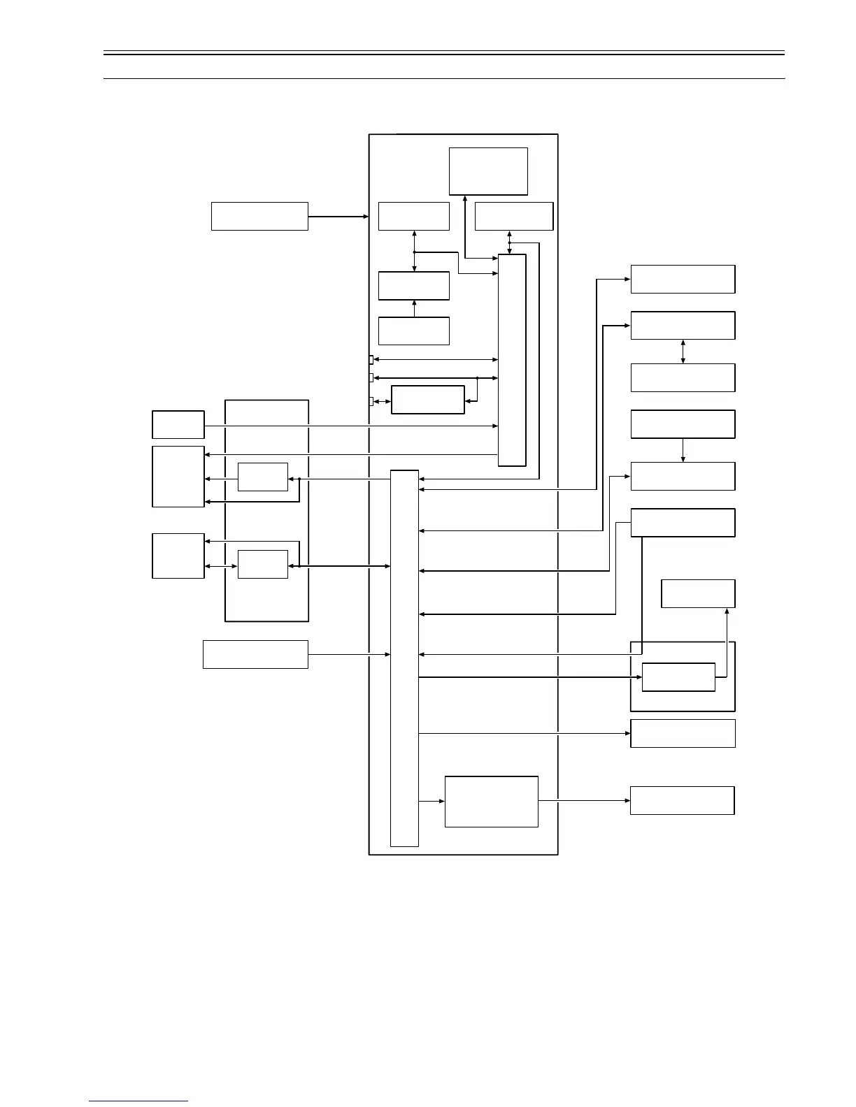
2.1 Basic Operation Outline
2.1.1 Printer Diagram
0017-4679
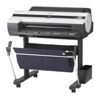
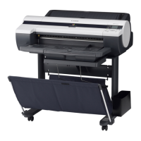
Shown below is a printer diagram.
F-2-1
Main controller PCB
Roll cam sensor
Roll media sensor
Suction fan
Mist fan
Roll feed unit PCB
Roll motor
Power supply PCB
USB
IEEE1394 Board
LAN
IC802
EEPROM
IC803
RTC
IC1201
LAN Controller
BAT 801
Lithium battery
IC701
FLASH ROM
IC1
ASIC
IC2
ASIC
Carriage PCB
Linear
encoder
Head
IC1
IC6/IC7
Multi
sensor
Operation panel PCB
Maintenance cartridge
relay PCB
Ink tank
ROM PCB
IC1
Motor driver
Fan
Ink tank
Sensor
Sensor /Switch
Motor
Motor
Maintenance cartridge
ROM PCB
IC601/IC602
IC603/IC604
IC301/IC302
SDRAM
Valve open /closed detection sensor
Feed roller HP sensor
Feed roller encoder sensor
Lift cam sensor
Paper detection sensor
Cutter right position sensor
Spur cam sensor
Pump cam sensor
Pump encoder sensor
Ink detection sensor
Temperature/humidity sensor
Head management sensor
Top cover sensor
Cutter HP sensor
Cassette encoder sensor
Cassette paper detection sensor
Cassette cam sensor
Cassette pick-up sensor
Cassette detection sensor
Cutter lift sensor
Ink tank cover switch
Carriage motor
Feed motor
Lift motor
Purge motor
Valve motor
Spur motor
Cutter motor
Cutter lift motor
Cassette motor
IC2801/IC2901
IC3001/IC3101
IC3901
Motor driver
CN2 J1801
J2511/J2512
J2712/J3011
J3202/J3211
J3411/J3911
J21/J22
J23
J3402
J3701/J3801
J3
J5
J2601
J2512
J2703
J2511/
J2512
J2511/J2712
J2801/J3011
J3101/J3211
J3911
J3
J1
J3202
J2/J3