MVX250i E, MVX200i E, MVX200 E
SERVICE MODE · ADJUSTMENT
20
5-3 IS Section Adjustment
Note)
(1) Perform the IS adjustment after machine is re-assembled to a product status.
(2) Prepare a tripod or stable work bench.
(3) Each of the adjustment data (5-3-1, 2) becomes valid when 5-3-3 data writing is made. After completion of each adjustment, be
sure to carry out 5-3-3 before turning power OFF.
5-3-1 Gyro Offset Adjustment
SPEC. Automatic adjusutment
Procedure)
(1) Wait at least 10 seconds while being careful not to apply vibration to the camera.
(2) Referring to the table shown below, perform the automatic adjustment.
Note)
It will take approx. 25 seconds at maximum to complete adjustment (OK) after storing (pressing the pause button).
5-3-2 Gyro Gain Check
Procedure)
(1) Referring to the table shown below, carry out data checkup.
STEP PROCEDURE Microcomputer operation
GYRO OFFSET CS Function MD ADDR DT ST
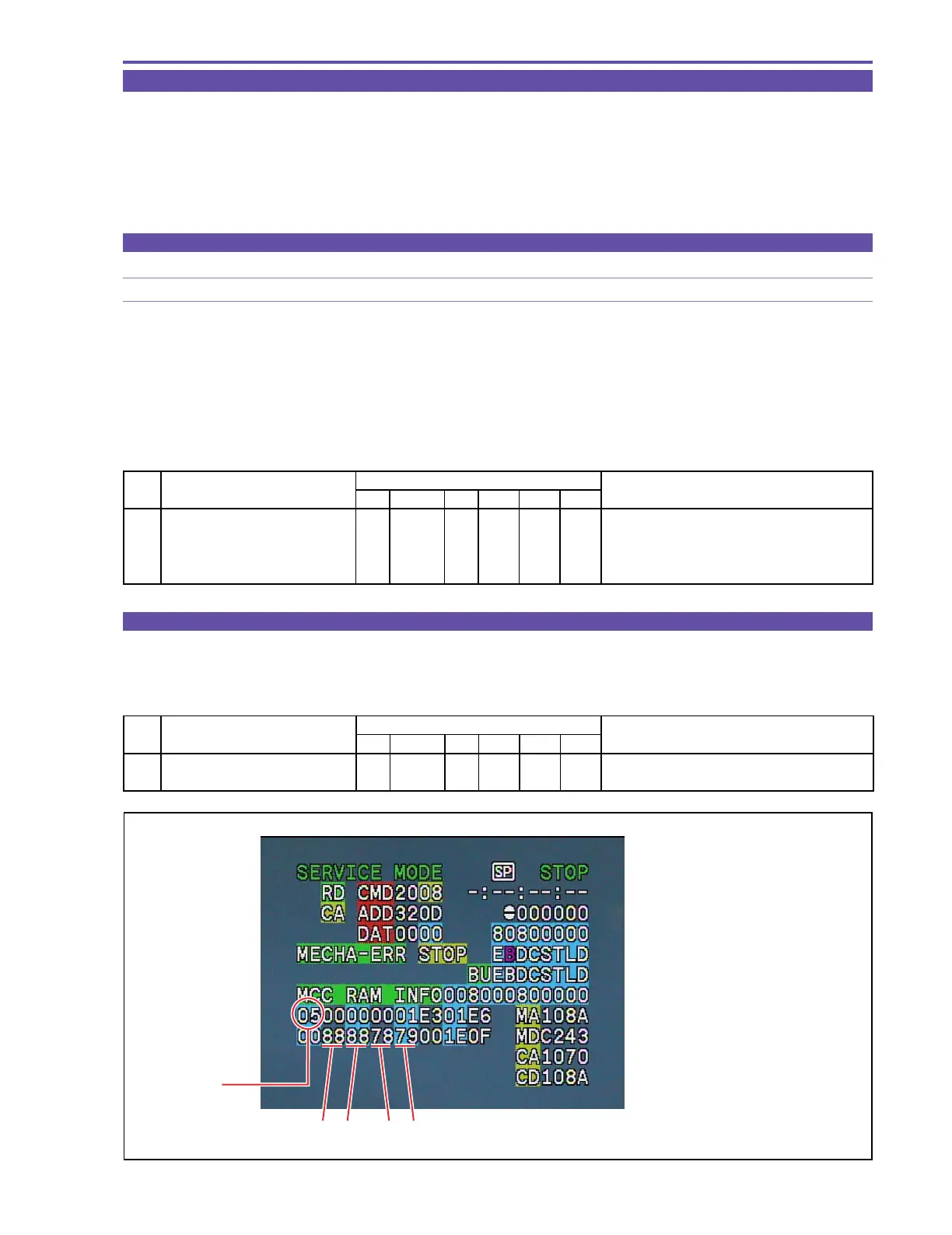
1 1) Make the setting shown at right. 2 08 RD 320D -- Check that IS1 = IS2 = 88.
2) Check data.
MONITOR
STEP PROCEDURE Microcomputer operation
GYRO OFFSET CS Function MD ADDR DT ST
1 1) Make the setting shown at right. 2 08 ST 320D 00
2) Perform storing.
↑↑
RD
↑
05 Adjustment is completed.
(press the PAUSE button.) Completion with ST:05, NG with ST:09
After adjustment, data is indicated at IS3 and IS4.
MONITOR
IS1 : Yaw Gyro gain
IS2 : Pitch Gyro gain
IS3 : Yaw Gyro offset
IS4 : Pitch Gyro offset
ST
IS4IS3IS2IS1
Fig. 17