MVX250i E, MVX200i E, MVX200 E
SERVICE MODE · ADJUSTMENT
35
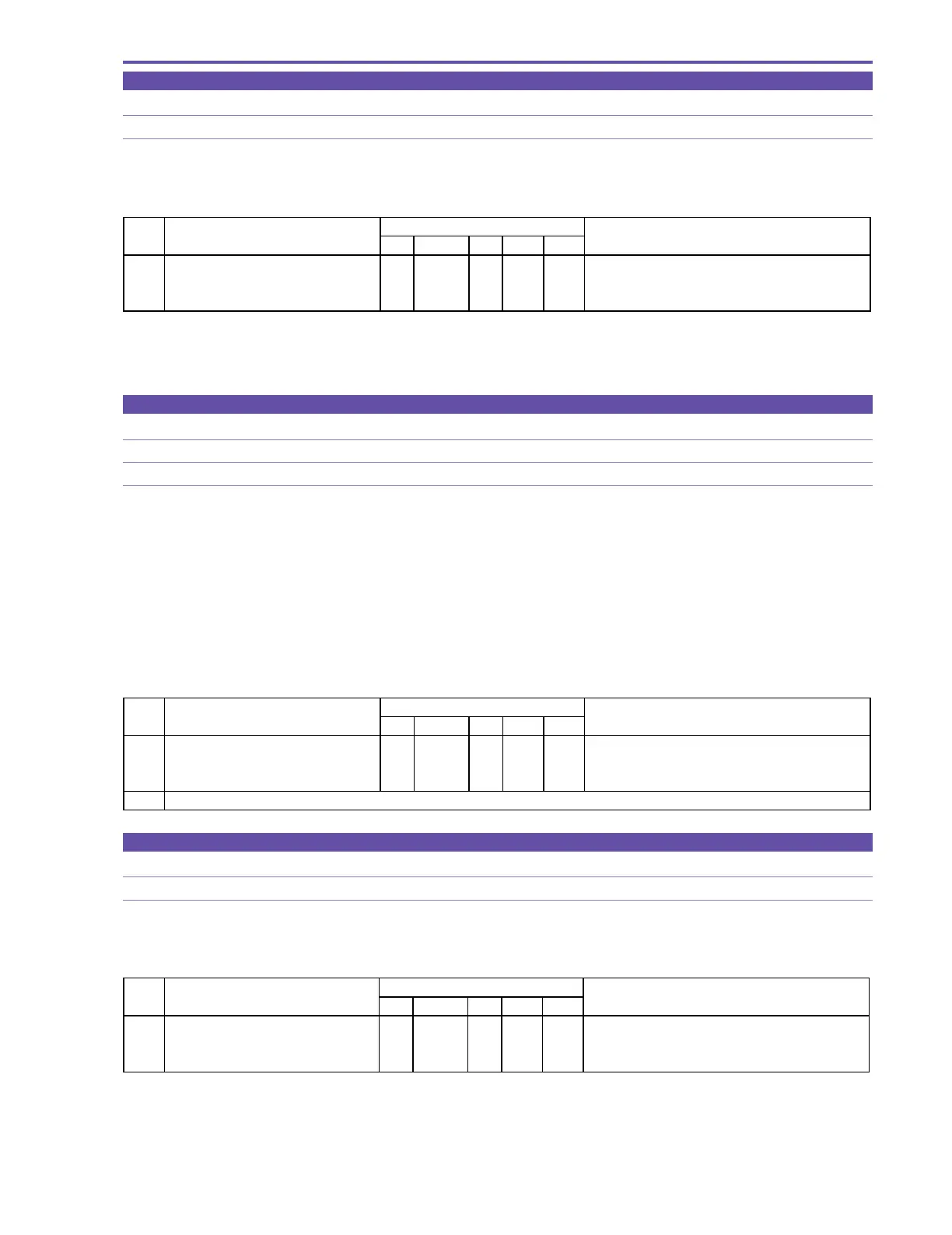
5-8-3 Automatic Adjustment of Reel FG
MODE Stop without VTR cassette
Procedure)
(1) Carry out reel FG adjustment according to the following table.
STEP PROCEDURE MONITOR Microcomputer operation
CS Function MD ADDR DT
1 1) Make the setting shown at right. 0 08 ST 0007 --
2) Perform storing.
↑↑
WR
↑↑
Aut omatic adjustment is in progress.
(press the PAUSE button.)
㸡㸡
RD
㸡㸡
Automatic adjustment is completed.
5-8-4 Battery Voltage Drop Adjustment
MODE During camera recording in product condition (AF : OFF, LCD PANEL : ON)
SPEC. Power supply voltage: 5.85 ± 0.02 [V]
Note)
(1) Perform the adjustment after 4sec of recording start.
(2) In step 1 - 2), after completion of storing, "ST" remains indicated or "WR" is indicated momentarily and then "ST" is indicated
again without returning to "RD". Be sure to check in step 2 that the adjustment has been completed.
Procedure)
(1) Under the above condition, set a power supply voltage to 5.85 ± 0.02[V].
(2) Referring to the table shown below, carry out battery voltage drop adjustment.
5-8-5 Flash Memory Writing
SPEC. Memory data writing
Procedure)
(1) Write adjustment data (5-8-1 to 4) into the flash memory according the table shown below.
STEP PROCEDURE Microcomputer operation
CS Function MD ADDR DT
1 1) Make the setting shown at right. 0 08 ST 0081 -- Preparation for flash memory updating.
2) Perform storing.
↑↑
RD
↑↑
Execution of flash memory updating.
(press the PAUSE button.)
MONITOR
STEP PROCEDURE MONITOR Microcomputer operation
BAT TERY VOLTAGE DROP. CS Function MD ADDR DT
1 1) Make the setting shown at right. 1 08 ST 0001 --
2) Perform storing.
↑↑
RD
↑↑
(press the PAUSE button.) Adjustment is completed.
2 Check if the value of DT is updated on DT2 during STORE.