MVX250i E, MVX200i E, MVX200 E
SERVICE MODE · ADJUSTMENT
36
5-9 Tape Path Adjustment
Note)
(1) For tape path adjustment, the service mode setting is necessary. For the details of setting procedure, refer to the DMC III Section.
Preparation)
(1) For tape path adjustment, make the recorder adjustment setting (P. 2, 3).
Procedure)
(1) Referring to the table given below (STEPS 1, 2, 3), play back the tracking master (DY9-1345-000) for tape path adjustment.
At STEP 2, perform tracking shift by adjusting DT in a range of F0 to FF so that the RF envelope will be 70%.
(2) After adjustment, restore tracking shift setting to normal according to the following table (STEPS 4 : P.OFF).
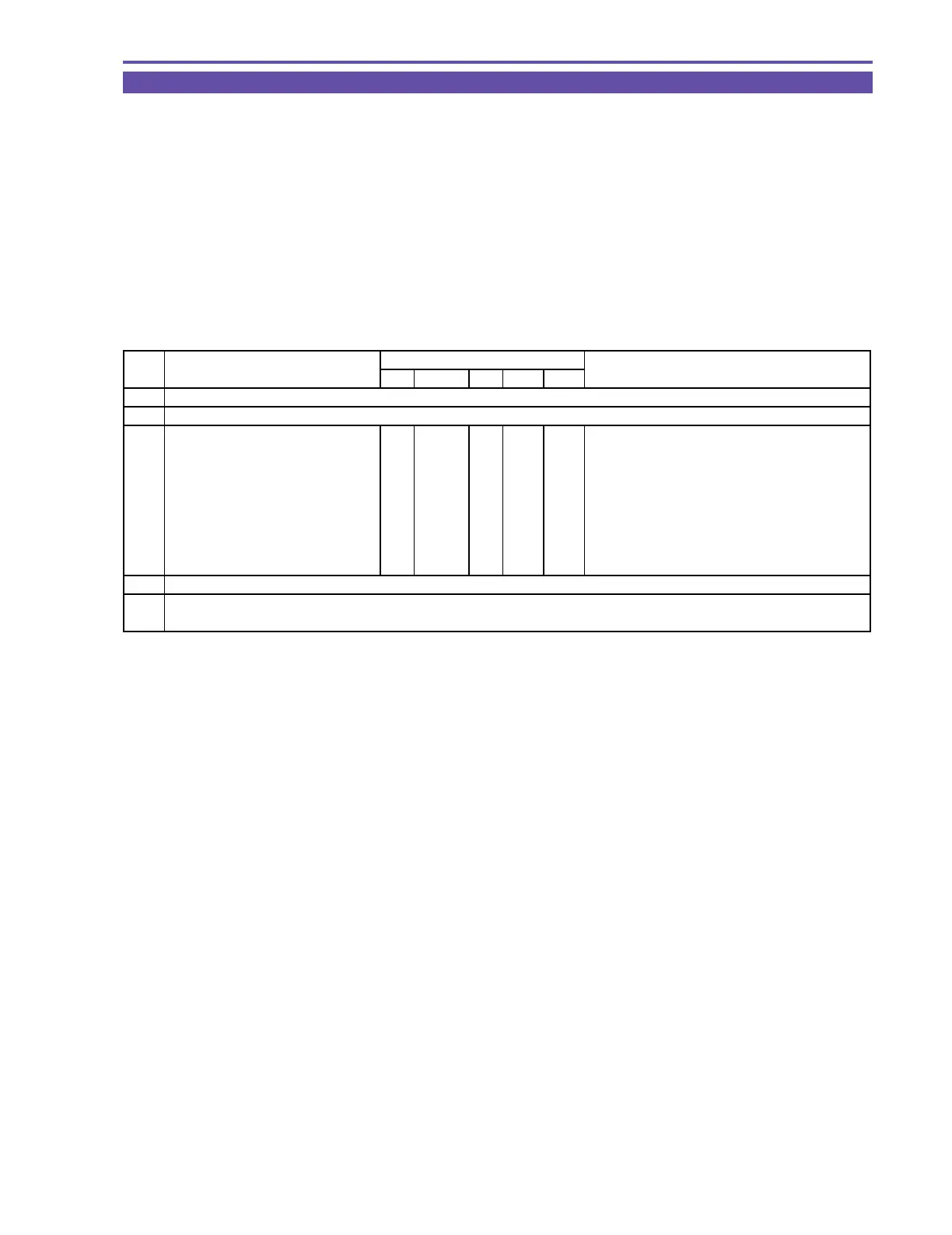
STEP PROCEDURE Microcomputer operation
TRACKING TAPE CS Function MD ADDR DT
1 1) Play back the tracking tape.
2 1) Set up tracking shift.
2-1 1) Make the setting shown at right. 0 00 ST 9FE7 F2
2) Perform storing.
↑↑
RD
↑↑
(press the PAUSE button.)
3) Perform 70% tracking shift by
↑↑
ST
↑
F0~FF The amount of tracking shift is changed.
adjusting DT in a range of F0 to FF.
4) Perform storing.
↑↑
RD
↑↑
(press the PAUSE button.)
* Tracking shift released in DT 00.
3 1) Perform tape path adjustment with the RF envelope in 70% tracking shift state.
4 1) Select the normal mode.
2) Turn off power to the main unit.
MONITOR