Appendix
104 105
AC Adapter
Model
Input
Output
Polarity
Size
Weight
PA-V16
100-240 V AC, 50/60 Hz
13.3 V DC, 1.8 A (max.)
Exterior (-), interior (+)
58 x 118 x 25 mm (2
5
/
16
x 4
21
/
32
x 1 in.) (W x D x H) (excluding attachments)
Approx. 205 g
● These specifications are subject to change without notice due to product improvements, etc.
VB101
Software
Operating System
DRYOS (Canon realtime operating system)
Protocols
TCP/IP, HTTP, BOOTP, FTP and SMTP
Video
compression method
Video compression rate
Output image sizes
Display image sizes
Log management
Camera control
Connection limitation
Motion-JPEG (image quality settings variable from 1 to 99)
JPEG (for still images)
0.1 to 30 fps (variable)
160 x 120, 320 x 240, 640 x 240 (pixel)
80 x 60, 160 x 120, 320 x 240, 640 x 480 (pixel)
Syslog format (supports email, syslog and flash memory cards)
External I/O 2 inputs, 2 outputs
Pan, tilt, zoom, brightness, shutter speed, focus mode, view restriction,
scheduling of camera control authority
(Canon VC-C4, VC-C4R, VC-C3, VC-C1 MK- II)
Access control (password/host), maximum view time, service period,
number of concurrent connections (max. 20)
Interface
Video input
Serial
Network
Card slots
Display LEDs
4 (NTSC/PAL, BNC (2), RCA (2))
RS-232C (3) (mini-DIN8, camera control (2), initial setup (1))
Ethernet (1) (RJ45, 10/100 auto-negotiation, PSTN (1 card slot),
2 slots (5V)
Power, Network and Card Slot status display
Main unit
specifications
Dimensions
Weight
Operating environment
Power supply
248 x 165 x 52 mm (9
13
/
16
x 6
1
/
2
x 2
3
/
32
in.) (W x D x H)
(excluding attachments)
1.3kg
Temp.: 0-40°C; Humidity: 20-85% RM (condensation free)
AC adapter, power consumption 25 W or less
● DRYOS is a realtime OS built into Canon products and intended for the Internet and an
intranet mobile devices and digital office equipment.
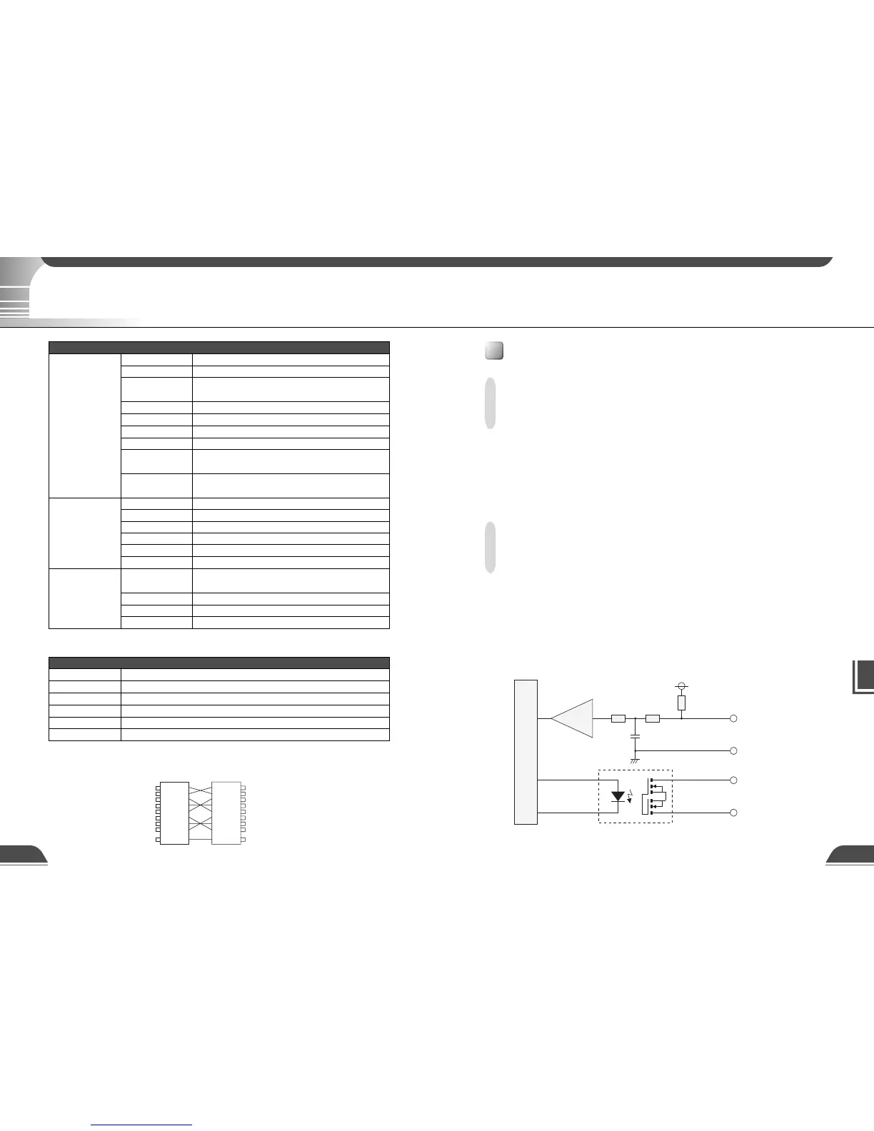
74LVC14
+3.3V
0.1µF
10kΩ 10kΩ
10kΩ
Internal controller
Input terminals
In1, In2
Output terminals
Out1, Out2
+
-
Specifications
External Device I/O Terminals
External Device Input Terminals (In1, In2)
The external device input terminals consist of 2 terminals (In1 and In2), one of which is '+' (red) and
another is '-' (black). The '-' terminal is grounded on the inside of the main unit. By connecting two
cables to the + and – terminals and then electrically short-circuiting across the terminals (ON) or
separating the connection (OFF), an interrupt can be generated for the internal controller. See "Picture
Recording and External Device I/O Settings Page" in Chapter 3 "Setup Procedures" (→ P.45) for
information on the settings.
Connect any sensors and switches to terminals with electrically separate GND terminals and
power supplies.
External Device Output Terminals (Out1, Out2)
The external device output terminals consist of 2 white terminals (Out1 and Out2). Both terminal
combinations are peers. The Internal controller switches the two output terminals to disconnected
or connected condition. The output terminals use optocouplers and are separate from the internal
circuit in the VB101. Loads connected to the output terminals should be within the following
ratings:
Rating across the output terminals: Up to 50 V DC
Continuous load current: 200 mA
■Internal Connection Chart
Specifications
Wire connection of the camera control cable (RS-232C)
Male 8pin mini-DIN Male 8pin mini-DIN
1
2
3
4
5
6
7
8
Frame
1
2
3
4
5
6
7
8
Frame