Before Using the VB101
1
18 19
Dc In
In Out
100/10BT
CC1
RS232C
Video In
Ethernet
CC2 V1 V2 V3 V4
Slot-A
Slot-B
12 21
Power connection socket
External device I/O terminals
Card slot A
(accepts modem card)
Card slot B
(accepts modem card)
100/10 BT Ethernet connector
(100Base-TX, 10Base-T automatic detection and switching)
Console connector terminal
for initial setup and servicing
(RS-232C)
Camera control connector CC1,
CC2
(RS-232C, with one touch lock)
Video input sockets V1, V2
(RCA pin-jack)
Video input sockets V3, V4
(BNC connector)
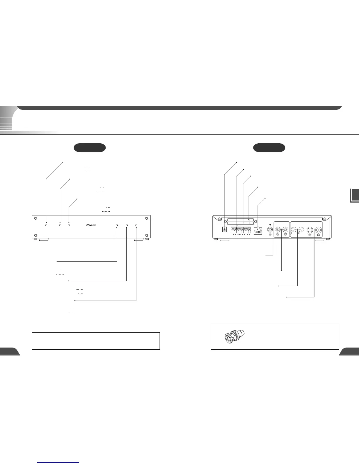
Slot-APower
VB 1
01
Slot-B 100 Tx/Lnk Col/Rx
Power LED
Powered on lit green
System fault lit orange
Slot-A LED
(Shows the operation status for card slot A)
Normal operation lit green
During access lit orange
Slot-B LED
(Shows the operation status for card slot B)
Normal operation lit green
During access lit orange
100 LED
(Shows the Ethernet 100/10 operation mode)
100Base-TX lit green
10Base-T off
Tx/Lnk LED
(Shows the Ethernet transmission status)
Normal connection lit green
During transmission lit orange
Col/Rx LED
(Shows the Ethernet reciving status)
Receiving lit green
Collision lit orange
Rear View
e
Tip
The video cable supplied with the Canon Communication
Camera VC-C4/VC-C4R, VC-C3 and VC-C1 MK II is compatible
with the RCA pin-jack. To connect these cameras to a BNC
socket, use a third party Pin → BNC conversion adapter.
System Components and Their Operation
Front View
e
Tip
When you power on the VB101, the power LED glows orange for several
seconds and then turns green. This is normal and does not indicate a fault.
System Components and Their Operation