Using the Picture Recording Function
5
80 81
LAN
cable
Ethernet
RS-232C
cable
Video cable
(RCA)
Relay
output
Sensor
input
Camera
Dc In
In Out
100/10BT
CC1
RS232C
Video In
Ethernet
CC2 V1 V2 V3 V4
Slot-A
Slot-B
12 21
VB101
Ethernet
Sensor A
Lighting unit
VC-C4R
Power
supply
unit
Lighting unit
ON/OFF
Camera control
and video images
Door opening signal
Sensor B
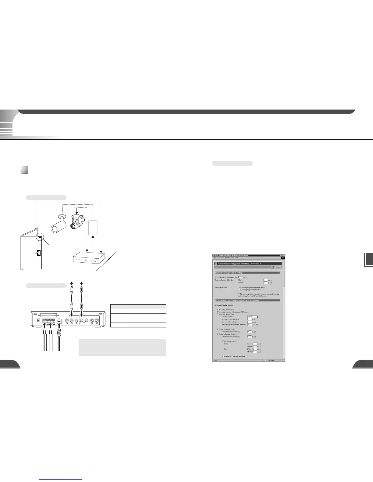
Connector Attached Cable
Sensors mounted on the door
In1
Lighting unit via the power supply unit
Out1
Video cable for the VC-C4R camera
V1
Control cable for the VC-C4R camera
CC1
Photography settings specified on the "Camera and Video" page (→ P.40)
Specify the appropriate settings for the camera 1 being used.
Photography settings specified on the "Preset" page (→ P.44)
Set a camera angle that shoots the open doorway as preset 1.
Photography settings specified in "External Device Input 1/2" (→ P.45)
● Set the photography operation time from 17:00 to 6:00.
● Give priority to "Recording triggered by external device".
● Set the camera position for shooting to preset 1.
● Set the light to switch on when the door opens and to switch off 20 seconds after the door closes.
● Begin recording pictures 4 seconds before the door opens. The light is not switched on at that point.
● Continue to record pictures for 8 seconds after the door closes.
● Record pictures at 10-second intervals while the door is open.
●
Delete the recorded pictures at 12:00 on the next day. In this case, delete the pictures recorded in the
morning at 12:00 on the next day, and delete the pictures recorded in the afternoon at 12:00 two days later.
Sample Settings
Using the Still Picture Recording Function Linked to an External Device
This is a monitoring system in which the lighting unit needed to take pictures switches on when the
door opens and the VC-C4R camera mounted on the ceiling captures still images. The equipment
shown in the figure below is connected to the terminals on the back of the VB101 at installation.
Sample application in combination with a door-opening sensor and lighting unit
By using the "External Device Input 1/2" setting and connecting devices such as sensors and switches to
the VB101, you can construct a monitoring system that operates in response to external changes. The still
images captured in this way are recorded on a memory card inserted into the VB101.
Installation Example
When the door opens and
Sensor B moves away from
sensor A, connection input
In1 generates an ON event.
In response to this event,
Out1 is controlled to switch
on the lighting unit and
images of the entrance are
captured and recorded by
the camera.
VB101 Connection Example
Using the Still Picture Recording Function Linked to an External Device
c
Note
Do not directly connect the power cord for the
lighting unit to OUT1 or OUT2.