Setup Procedures
3
30 31
1
2
3
4
Enclosed CD-ROM
RS-232C cable to
be used for setup
PC
VB101
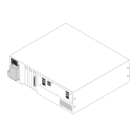
Select the connection port. Switch the VB101 off and then on again.
Enter "VB101" as the password
(Factory initial setting).
Enter the IP address, subnet mask,
and gateway address.
On some PCs you
may have to select a
port other than COM1.
Check the port number
to which the serial
cable is connected.
1
2
3
4
1
2
3
4
VB101
Camera
VB101
Camera
VB101
Camera
Installation Example
VC-C4
COMMUNICATION CAMERA
f:4-64mm 1:1.4-2.8
VC-C4
COMMUNICATION CAMERA
f:4-64mm 1:1.4-2.8
VC-C4
COMMUNICATION CAMERA
f:4-64mm 1:1.4-2.8
VC-C4
COMMUNICATION CAMERA
f:4-64mm 1:1.4-2.8
VC-C4
COMMUNICATION CAMERA
f:4-64mm 1:1.4-2.8
VC-C4
COMMUNICATION CAMERA
f:4-64mm 1:1.4-2.8
VC-C4
COMMUNICATION CAMERA
f:4-64mm 1:1.4-2.8
VC-C4
COMMUNICATION CAMERA
f:4-64mm 1:1.4-2.8
VC-C4
COMMUNICATION CAMERA
f:4-64mm 1:1.4-2.8
VC-C4
COMMUNICATION CAMERA
f:4-64mm 1:1.4-2.8
VC-C4
COMMUNICATION CAMERA
f:4-64mm 1:1.4-2.8
VC-C4
COMMUNICATION CAMERA
f:4-64mm 1:1.4-2.8
Initial Setup
Connect the VB101 to the PC to
be used for initial setup by
using bundled RS-232C cable.
Switch the VB101 and the PC on.
The power lamp on the VB101 turns to green. (→ P.18)
Insert the CD-ROM supplied with the VB101 into the PC and
launch the "VB101_IP.exe" program.
When the "VB101_IP.exe" dialog box appears, use steps
to
in the procedure below to enter the password, IP address,
subnet mask, and gateway address.
c
Note
● If you do not know the network settings, contact the network administrator.
● When you click the [Cancel] button after switching the VB101 back on, the
power LED remains lit orange. At this point, the VB101 software has not
started up. If you do not need to change the settings, switch the VB101 off
and then on again, and check that the power LED turns green. To begin the
setup procedure again, launch "VB101_IP.exe" and then switch the VB101
off and on again as directed by the on-screen instructions.
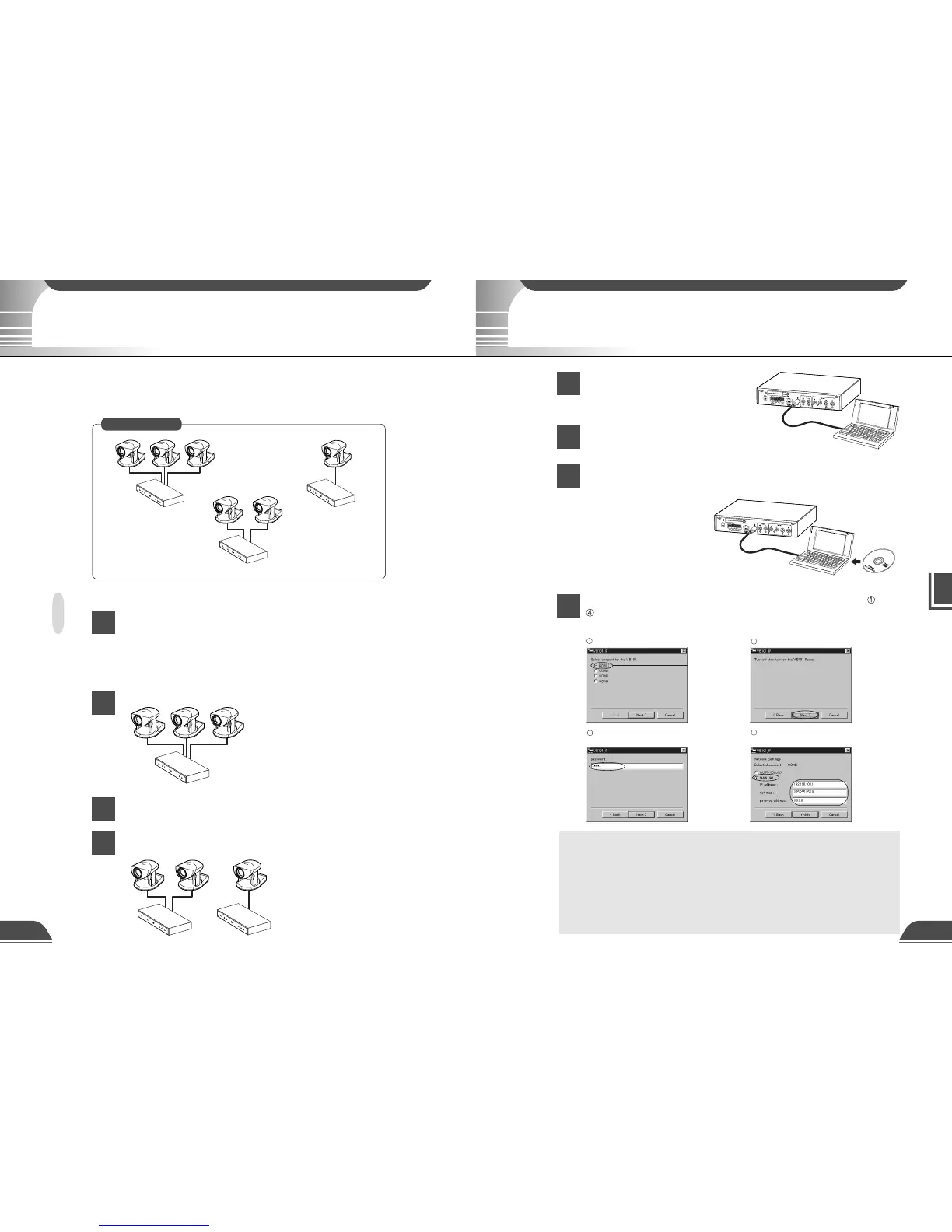
Installation Workflow
Once the initial setup has been completed and operation has been verified, the
VB101 can be used immediately. This section describes the installation procedure
for 3 VB101s and 6 cameras, as shown in the figure below.
Installation Procedure
Perform initial setup for all the VB101s (→ next page).
You should determine the IP address and password for each unit beforehand. You
should then set these for each VB101 and create the web page before transporting the
VB101 to the installation site (→ Chapter 4).
Install the VB101 and the cameras. (→ Chapter 2)
Check the operation. (→ P.33)
Install the remaining VB101 units in the same way and check
that they are operating normally.
Up to 2 cameras can be controlled.
Connect RS-232C cables to control
connectors CC1 and CC2 on the cameras
to be controlled (→ P.24).