15
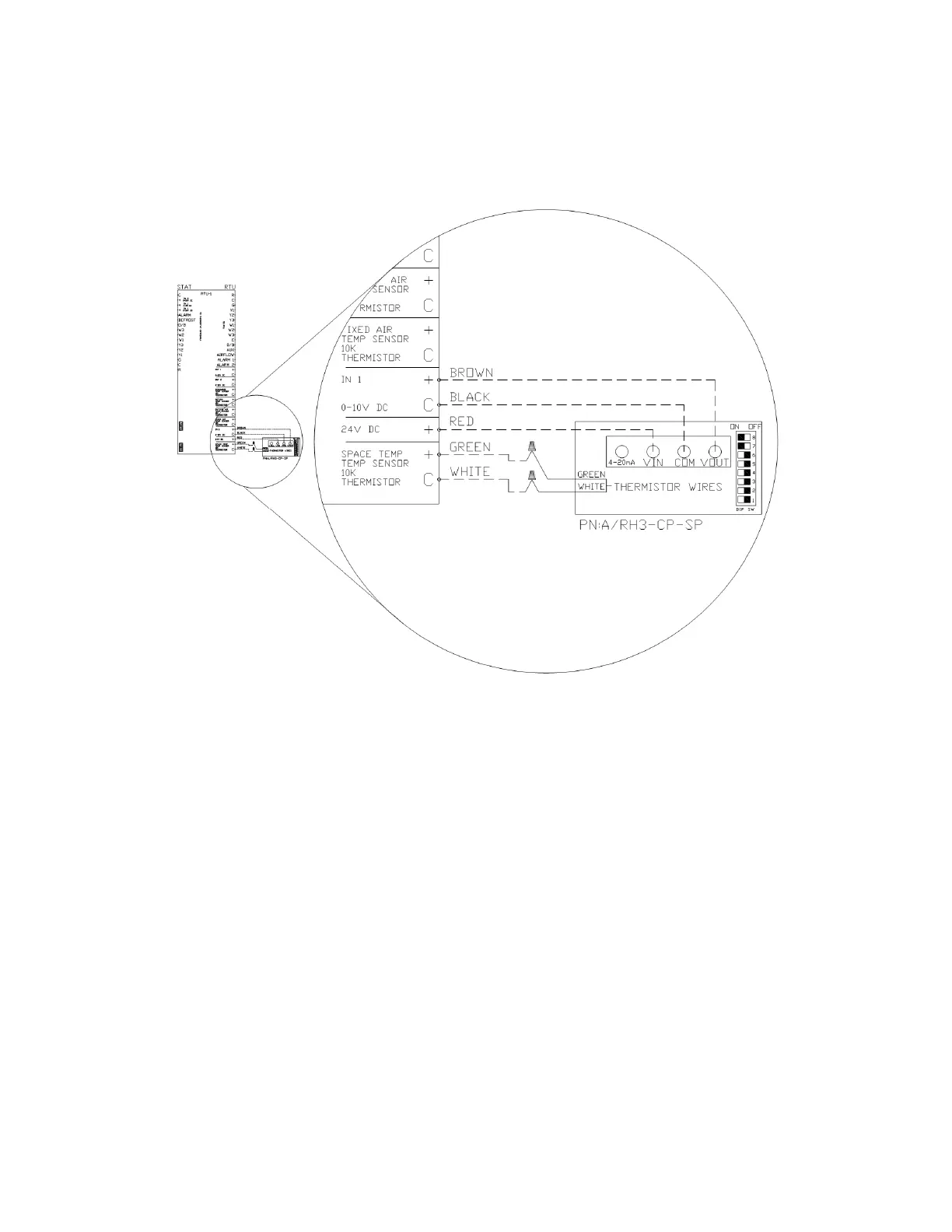
The sensor has a bank of eight dip switches that control the range of the output voltage of the humidity sensor. Switches
seven (7) and eight (8) need to be turned ON, and the rest should remain OFF. These dip switches can be seen in the
sensor detail in Figure 14.
Once the sensor is wired to an input, enter the configuration menu of the RTULink via the onboard HMI and configure the
corresponding input for the humidity sensor that was installed. In the Figure 14 example, “RTU IN 1” would be configured
for “SPACE RH”.