19
ENG
“compactsteam” +0300092IE - rel. 1.2 - 14.01.2021
3.10 On/Off operation
The diagrams shown in the gures on the side indicate the connections
to be performed on the terminal block in the following situations:
Fig 3.x operation controlled by a simple voltage-free remote enabling
contact, indicated as CR;
Fig 3.y operation controlled by an external mechanical humidistat,
indicated as H;
Fig 3.z a combination of the above.
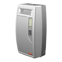
Remote enabling contact (g.3x)
Remove the jumper between terminals AB-AB and connect the voltage-
free remote contact (CR) in series to terminals AB-AB; terminals IN-GND
must be jumpered. When contact AB-AB is closed, the humidier is
enabled for operation; if the contact is open, steam production stops
immediately.
Fig. 3.x
External humidistat without enabling (g. 3.y)
Connect the external humidistat between terminals IN-GND and leave
the jumper in position between terminals AB-AB. DO NOT apply any
voltage to AB-AB. If the IN-GND contact is closed, steam production
starts, while if it is open steam production stops after 5 s.
N2
G ND
N1
AB
AB
G ND
IN
H
Fig. 3.y
External humidistat with enabling (g. 3.z)
Connect the external humidistat between terminals IN-GND. Remove
the jumper between terminals AB-AB and connect any limit devices,
air ow switches or remote contacts (CR) in series to terminals AB-AB.
Steam production only starts when both contacts, AB-AB and IN-GND,
are closed. If contact AB-AB is open steam production stops immediately,
while if IN-GND is open production stops after 5 s.
C R (1)
N2
G ND
N1
AB
AB
G ND
IN
H
Fig. 3.z
Interlock between compactSteam for ducts and the system
fan controller
In duct applications, compactSteam starts steam production only if
there is an external call for humidity (humidistat closed) and the system
fan is on. The system fan communicates with compactSteam via the
remote input AB-AB. The following sequence of events must be true for
compactSteam to produce steam:
• External humidistat close (= steam demand);
• FAN-EXT contact closed by compactSteam, to start the system fan;
• Input AB-AB closed, indicating that the fan has started (= enable steam
production).
compactSteam can be connected to an air ow switch (that is, a device
that senses the ow of air generated by the fan in the duct). This ow
sensor should be connected to the remote enabling input (terminals
AB-AB) in series with a limit humidistat (normally closed). When the ow
sensor is connected to compactSteam, steam production is only enabled
if air ow is measured inside the duct.
Fan symbol
• O: no call (IN-GND = open), regardless of whether or not production
is enabled (AB-AB = open or closed);
• Flashing: call present (IN-GND = closed), awaiting production to be
enabled (AB-AB = open);
• On steady: call present (IN-GND = closed) and production enabled
(AB-AB = closed).
Note:
• When enabled (AB-AB = closed), the symbol goes o 30 s after the
production call is no longer present (IN-GND = open);
• When the production call is present (IN-GND = closed), the symbol
goes o 60 s after production is disabled (AB-AB = open).
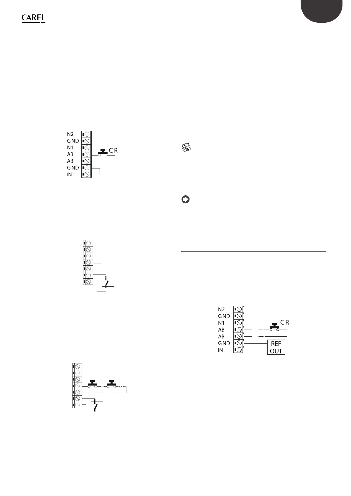
3.11 Modulating operation
Connect the external 0 to 10 V modulating control device between
terminals IN-GND as shown in Fig. 3.v. Then connect any safety switches
(limit device, air ow switch, remote on/o) in series to terminals AB-AB.
If no safety switches are used, install a jumper between AB-AB. DO NOT
apply any voltage to AB-AB.
Steam production is modulated from 20% to 100% of the maximum
production, proportionally to the signal provided by the external
controller.
Fig. 3.aa