13ir33 platform “connections” +030220445 - rel. 2.3 - 27.04.2011
74
93
21
8
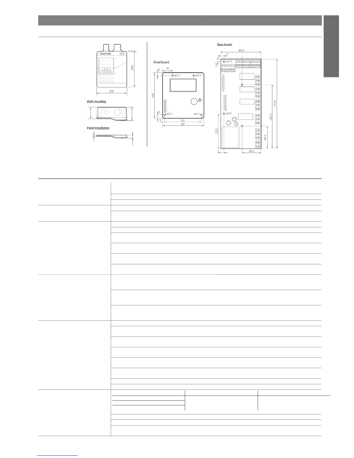
Fig. 3.a
ENGLISH
3. MASTERCELLA 2
3.1 Dimensions
3.2 Technical specifi cations
voltage power
Power supply
model E: 230 V~ 50/60 Hz; 11,3 VA, 50 mA~ max
model A: 115 V~ 50/60 Hz; 11,3 VA, 100 mA~ max
Insulation guaranteed by the power supply
voltage power
model E, A:
insulation from very low voltage parts reinforced; 6 mm air, 8 mm surface; 3750 V insulation
insulation from relay outputs basic; 3 mm air, 4 mm surface; 1250 V insulation
Inputs S1 NTC or PTC, depending on the model
S2 NTC or PTC, depending on the model
DI1 voltage-free contact, contact resistance < 10 ohm, closing current 6 mA
S3 NTC or PTC, depending on the model
DI2 voltage-free contact, contact resistance < 10 ohm, closing current 6 mA
S4 NTC or PTC, depending on the model
DI3 voltage-free contact, contact resistance < 10 ohm, closing current 6 mA
S5 NTC or PTC, depending on the model
Maximum distance between probes and digital inputs less than 10 m. Note: in the installation, keep the power supply and load connec-
tions separate from the probe, digital inputs, repeater display and supervisor cables.
Type of probe Std. Carel NTC 10 k at 25 °C, range -50 to 90 °C
measurement error: 1 °C in the range -50 to 50 °C
3 °C in the range +50 to 90 °C
High temperature NTC 50 k at 25 °C, range -40 to 150 °C
measurement error: 1.5 °C in the range -20 to 115 °C
4 °C in the range outside of -20 to 115 °C
Std. Carel PTC (specifi c model) 985 at 25°C, range -50 to 150 °C
measurement error: 2 °C in the range -50 to 50 °C
4 °C in the range +50 to 150 °C
Relay outputs depending on the model
8 A (*) EN60730-1: 250 V~ 8 (4) on N.O., 6 (4) on N.C., 2 (2) on N.O. and N.C.; 100,000 operating cycles
UL 873: 250 V~ 8A res 2FLA 12LRA C300; 30,000 operating cycles
16 A (*) EN60730-1: 250 V~ 10 (4) A up to 60°C on N.O., 12 (2) A on N.O. and N.C.;100,000 operating cycles
UL 873: 250 V~ 12A res 5FLA 30LRA C300; 30,000 operating cycles
2HP EN60730-1: 250 V~ 10 (10) A; 100,000 operating cycles
UL 873: 250 V~ 12A res 12FLA 72LRA; 30,000 operating cycles
30 A (*) EN60730-1: 250 V~ 12 (10) A; 100,000 operating cycles
UL 873: 250 V~ 12A res 2HP 72LRA; 30,000 operating cycles
(*): relay not suitable for fl uorescent loads (neon lights, ...) that use starters (ballasts) with phase-shift capacitors. Fluorescent lamps with
electronic control devices or without phase-shift capacitors can be used, within the operating limits specifi ed for each type of relay.
insulation from very low voltage parts reinforced; 6 mm air, 8 mm surface; 3750 V insulation
insulation between the relay outputs basic; 3 mm air, 4 mm surface; 1250 V insulation
Connections
Type of connection Cross-sections Maximum current
fi xed screw for cables from 0.5 to 2.5 mm
2
12A
plug-in for screw blocks
spade with crimped contact
wire cross-section for probes and digital inputs: 0.25 to 2.5 mm2 (from 20 to 13 AWG)
wire cross-section per power supply and loads: 1.5 to 2.5 mm2 (from 15 to 13 AWG)
The correct sizing of the power and connection cables between the instrument and the loads is the responsibility of the installer.
In the max load and max operating temp. conditions, the cables used must be suitable for operation up to 105°C.
 Loading...