16 ir33 platform “connections” +030220445 - rel. 2.3 - 27.04.2011
34.4
70.5
79
76.2
80.6
38.6
56.5
65
1
2
3
Fig. 4.a
ENGLISH
4. IR33
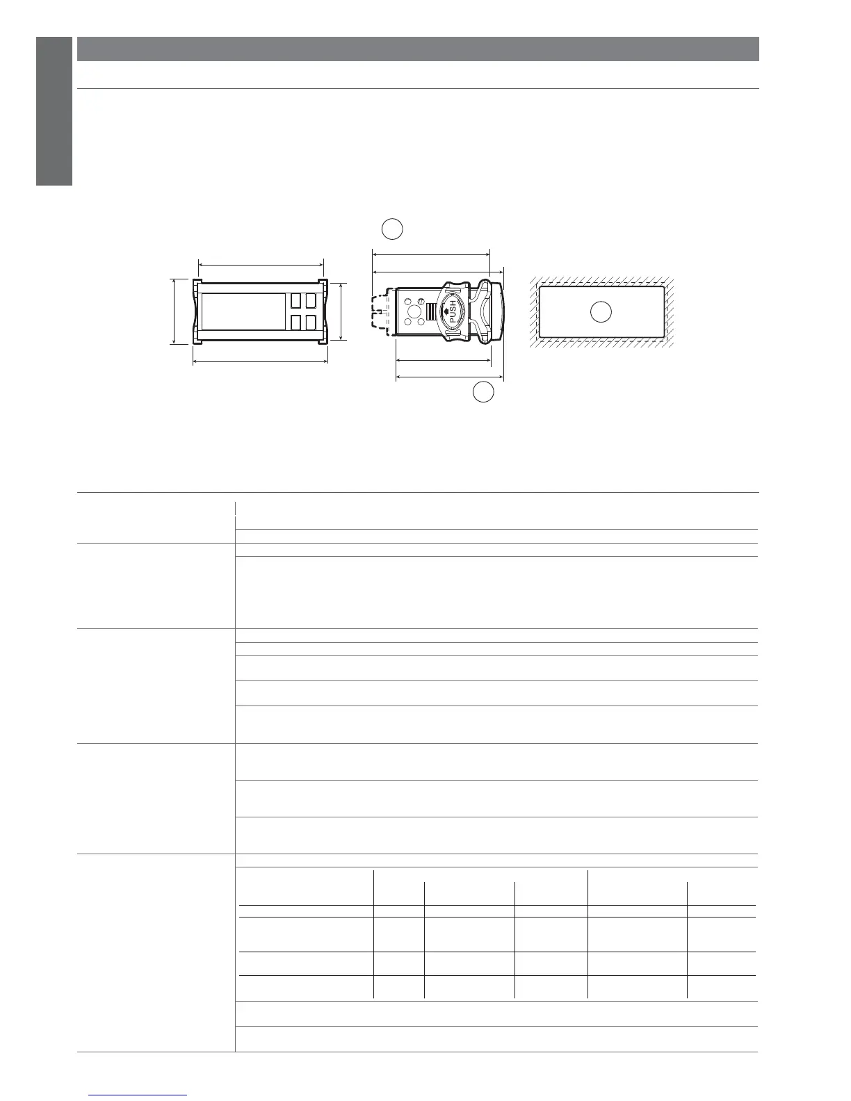
4.1 Dimensions
Appearance and ergonomics:
The appearance has been designed to fi t in harmoniously with the new lines of the refrigeration units.
The main characteristic is its compactness: the dimensions are in fact 34.4 x 76.2 x 65 mm, and 34.4 x 76.2 x 79 mm for the version with traditional transformer.
The drilling templates for both versions are 29 x 71 mm.
Key:
1. version O, L, H;
2. version E, A;
3. drilling template 71x29 mm
4.2 Electrical specifi cations
voltage power
Power supply
E: 230 V~ 50/60 Hz; 3 VA, 25 mA~ max
A: 115 V~ 50/60 Hz; 3 VA, 50 mA~ max
Insulation guaranteed by the power
supply
voltage power
E, A:
insulation from very low voltage parts reinforced; 6 mm air, 8 mm surface; 3750 V insulation
insulation from relay outputs for model E, A,
for I, L, M, N connections only basic; 3 mm air, 4 mm surface; 1250 V insulation
insulation from relay outputs for model E, A,
for A, B, C, D, E, F, G, H connections only basic; 3 mm air, 4 mm surface; 1250 V insulation
Inputs S1 NTC or PTC, depending on the model
S2 NTC or PTC, depending on the model
DI1 voltage-free contact, contact resistance < 10, closing current 6 mA NTC or PTC
S3 depending on the model
DI2 voltage-free contact, contact resistance < 10, closing current 6 mA NTC or PTC
S4 depending on the model
Maximum distance between probes and digital inputs less than 10 m
Note: in the installation, keep the power supply and load connections separate from the probe, digital inputs, repeater display and supervisor
cables.
Type of probe Standard Carel NTC 10 k at 25 °C, range -50T90 °C
measurement error: 1 °C in the range -50T50 °C
3 °C in the range +50T90 °C
High temperature NTC 50 k at 25 °C, range -40T150 °C
measurement error: 1.5 °C in the range -20T115 °C
4 °C in the range outside of -20T115 °C
Standard Carel PTC 985 at 25°C, range -50T150 °C
(specifi c model) measurement error: 2 °C in the range -50T50 °C
4 °C in the range +50T150 °C
Relay outputs depending on the model
EN60730-1 UL 873
modello relè 250V~ cicli di manovra 250V~ cicli di manovra
IRxxxx(E,A)(P,Q,S,U,V,X,Y,Z)xxx R2 (*) 5 (1) A 100000 5A res 1FLA 6LRA C300 30000
IRxxxx(E,A)(N,R,C,B,A,M,L,T)xxx R3(*) 5 (1) A 100000 5A res 1FLA 6LRA C300 30000
IRxxxx(E,A)(N,R,C,B,A,M,L,T)xxx
IRxxxx(0,L,H)(N,R,C,B,A,M,L,T)xxx
IRxxxx(0,L,H)(H,I,E,F,G,K,O,W))xxx
R1,R2
R2,R3,R4
R2,R3,R4(*)
8 (4) A su N.O.
6 (4) A su N.C.
2 (2) A su N.O. e N.C.
100000 8A res 2FLA 12LRA C300 30000
IRxxxx(E,A)(P,Q,S,U,V,X,Y,Z)xxx
IRxxxx(0,L,H)(N,R,C,B,A,M,L,T)xxx0
R1
R1(*)
12 (2) A su N.O. e N.C. 100000 12A res 5FLA 30LRA C300 30000
IRxxxx(0,L,H)(H,I,E,F,G,K,O,W))xxx R1 10 (10) A 100000 12A res 12FLA 72LRA
Toff minimum 60 seconds
30000
(*): relay not suitable for fl uorescent loads (neon lights, ...) that use starters (ballasts) with phase-shift capacitors. Fluorescent lamps with
electronic control devices or without phase-shift capacitors can be used, within the operating limits specifi ed for each type of relay.
insulation from very low voltage parts reinforced; 6 mm air, 8 mm surface; 3750 V insulation
insulation between the relay outputs indipendent basic; 3 mm clearance, 4 mm creepage; 1250 V insulation
 Loading...


