17ir33 platform “connections” +030220445 - rel. 2.3 - 27.04.2011
ENGLISH
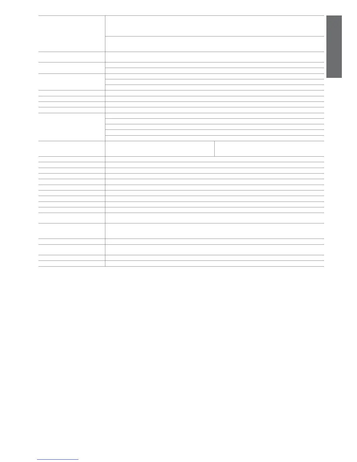
Connections
Type of connection Cross-sections Max current.
fi xed screw 16A for cables from 0.5 to 4.2 mm
2
16A
fi xed screw for cables from 0.5 to 2.5 mm
2
12A
estraibili per blocchetti a vite
The correct sizing of the power and connection cables between the instrument and the loads is the responsibility of the installer.
Depending on the model, the maximum current at the common terminals is 12A or 16A. In the max load and max operating temp. conditions,
the cables used must be suitable for operation up to 105°C.
Case plastic: E, A dimensions 34.4x76.2x65 mm - mounting depth 56.5 mm
O, L, H dimensions 34,4x76,2x79 mm - mounting depth 70,5 mm
Assembly smooth, hard and indeformable panel: side fastening brackets, to be pressed in fully
drilling template: dimensions 28.8 ± 0.2 x 70.8 ± 0.2 mm
Display digits: 3 digit LED
display: from -99 to 999
operating status: indicated with graphic icons on the display
Keypad 4 silicone rubber buttons
Infrared receiver available depending on the model
Clock with backup battery available depending on the model
Buzzer available in all models
Clock error at 25 °C: ± 10 ppm (±5.3 min/year)
error in the temperature range -10T60 °C: - 50 ppm (-27min/year)
ageing: < ± 5 ppm (±2.7 min/year)
discharge time: typically 6 months (8 months maximum)
recharge time: typically 5 hours (< 8 hours maximum)
Operating temperature IRxxxx(E,A)(P,Q,S,U,V,X,Y,Z)xxx
IRxxxx(E,A,0,L,H)(N,R,C,B,A,M,L,T)xxx
IRxxxx(0,L)(H,I,E,F,G,K,O,W))xxx
-10T60 °C
Operating humidity <90% RH non-condensing
Storage temperature -20T70 °C
Front panel index of protection assembly on smooth and indeformable panel with IP65 gasket
Environmental pollution 2, normal situation
PTI of insulating materials printed circuits 250, plastic and insulating materials 175
Period of stress across the insulating parts long
Category of resistance to fi re category D and category B (UL 94-V0)
Class of protection against voltage surges category II
Type of action and disconnection 1B relay contacts (micro-disconnection)
Construction of the control device electronic control device incorporated
Classifi cation according to protection
against electric shock
class II when appropriately integrated
Device designed to he hand-held or
integrated into equipment designed to
be hand-held
no
Software class and structure class A
Cleaning the front panel of the instru-
ment
only use neutral detergents and water
Serial interface for CAREL network External, available in all models
Programming key Available in all models
Table 4.a
 Loading...