23ir33 platform “connections” +030220445 - rel. 2.3 - 27.04.2011
ENGLISH
6.1 Dimensions
See “Dimensions” for the chapter on the ir33.
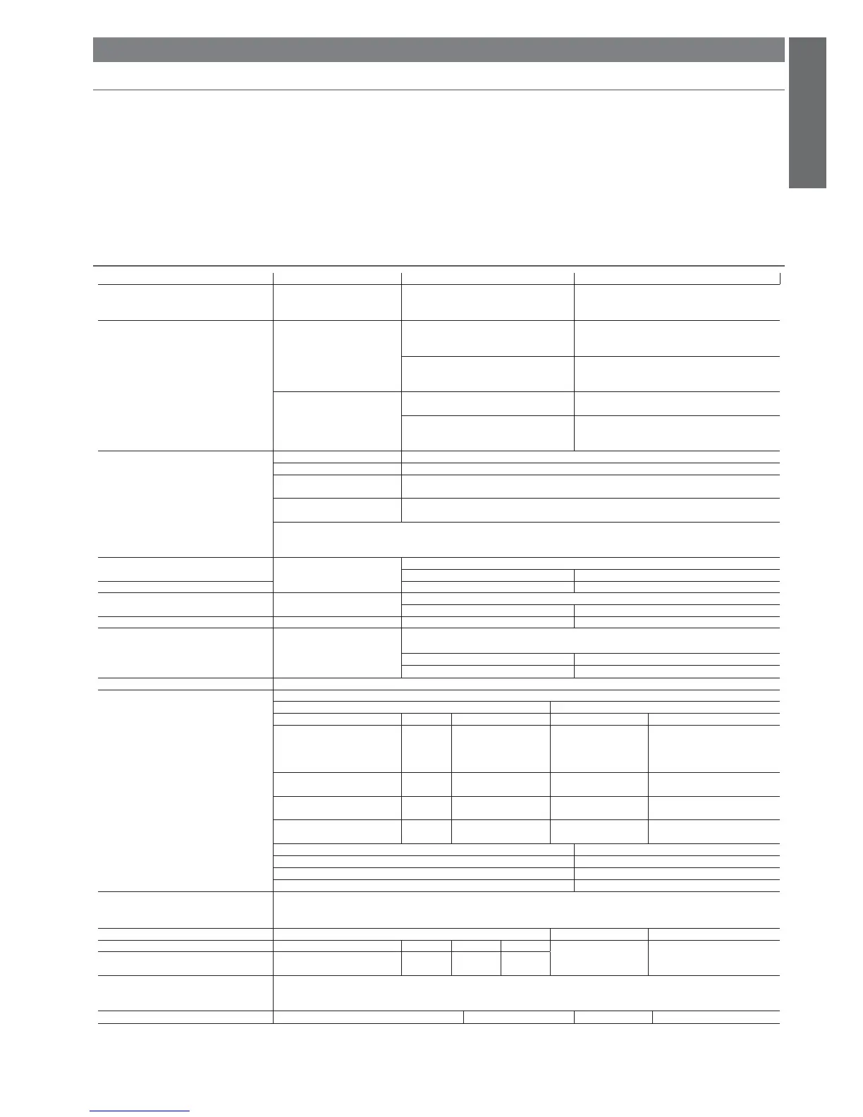
6.2 Technical specifi cations
Model Voltage Power
Power supply mod H:
mod L:
mod O:
115...230 V~, 50/60 Hz
12...24 V~, 50/60 Hz, 12...30 Vdc
12 V~, 50/60 Hz, 12...18 Vdc
6 VA, 50 mA~ max
3 VA, 300 mA~ /mAdc max
Use only SELV power supply
Insulation guaranteed
by the power supply
mod H:
insulation in reference
to very low voltage parts
reinforced
6 mm clearance, 8 creepage
3750 V insulation
insulation from relay outputs basic
3 mm clearance, 4 creepage
1250 V insulation
mod O, L:
insulation in reference
to very low voltage parts
da garantire esternamente
con trasformatore di sicurezza (SELV)
insulation from relay outputs reinforced
6 mm clearance, 8 creepage
3750 V insulation
Input S1 (probe 1) NTC (IRxxx0xxxxx) o NTC e PTC (IRxxx7xxxxx)
S2 (probe 2) NTC (IRxxx0xxxxx) o NTC e PTC (IRxxx7xxxxx)
DI1
S3 (probe 3)
free contact, contact resistance < 10 , closing current 6 mA
NTC (IRxxx0xxxxx) o NTC e PTC (IRxxx7xxxxx)
DI2
S4 (probe 4)
free contact, contact resistance < 10 , closing current 6 mA
NTC (IRxxx0xxxxx) o NTC e PTC (IRxxx7xxxxx)
Maximum ditance of probes and digital inputs less than 10 m.
Nota:during installation keep the power and loads connection separate from probe cables, digital inputs, repeater display and supervisory
system.
Probe type
NTC std. CAREL 10 k a 25 °C, range da –50T90 °C
measurement error: 1 °C in the –50T50 °C range
3 °C
in the –50T90 °C range
NTC high temperature 50 k a 25 °C, range da –40T150 °C
measurement error 1,5 °C in the –20T115 °C range
4 °C nel range esterno a -20T115 °C
PTC std. CAREL (
specifi c model)
985 a 25 °C, range da -50T150 °C
measurement error 2 °C in the –50T50 °C range
4 °C in the –50T150 °C range
Relay outputs Rating xdon the model IRxx(S,Y,F,C)x(0,L,H)(H,I,E,G,K,O,W)xxx
EN 60730-1 UL 873
relè 250 Vac operating cycles 250 Vac operating cycles
R1 10 (10)A 100000 12A resistive 12 FLA 72
LR, Toff minimum 60
seconds(*), pilot duty
C 300
30000
R2(**) 8 (4)A 100000 8A resistive 2 FLA 12 LRA,
pilot duty C300
30000
R3(**) 8 (4)A 100000 8A resistive 2 FLA 12 LRA,
pilot duty C300
30000
R4(**) 8 (4)A 100000 8A resistive 2 FLA 12 LRA,
pilot duty C300
30000
insulation from very low voltage parts reinforced
rinforzato: 6 mm in aria, 8 superfi ciali
3750 V isolamento
insulation between the relay outputs indipendent
principale: 3 mm in aria, 4 superfi ciali
1250 V isolamento
(*): between the OFF status and the following ON status of the relay at least 1 minute have to elapse.
(**): Relay not suitable for fl uorescent loads (neon lights, ...) that use starters (ballasts) with phase-shift capacitors. Fluorescent lamps
with electronic control devices or without phase-shift capacitors can be used, within the operating limits specifi ed for each type of relay.
Connections
Type of connection Cross-section Max. current
Model Relay P. Supply Probes for wires from 0,5 to
2,5 mm
2
12 A
0
2
screw/faston
removablei
screw
removable
screw
removable
the installer has to provide the correct dimensioning of the power supply and cable connection between the instruments and the loads.
Depending on the model, the maximum current in the common terminals 1, 3 or 5 is 12 A. When using the controller at maximum operating
temperature and full load, use cables featuring a maximum operating temperature of 105 °C at least.
Case plastic Models: O, L, H dimensions
34,4 x 76,2 x 79 mm
6. IR33 2HP
 Loading...