10 ir33 platform “connections” +030220445 - rel. 2.3 - 27.04.2011
183.4
39.4
40
28.2
45
AUX
165
153.5
WIDE
STANDARD
dima di foratura
drilling template
da 138.5 a 150 x 31mm
167
36
1
8
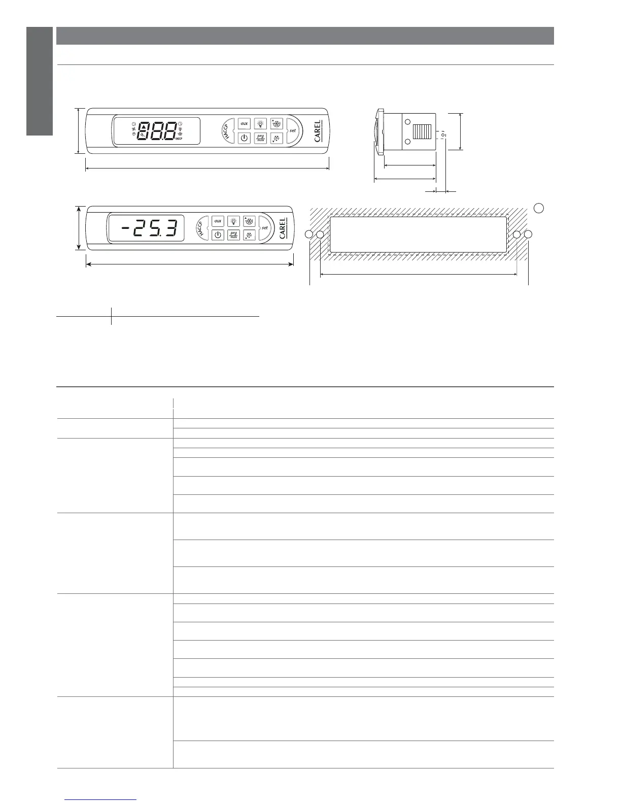
Fig. 2.a
ENGLISH
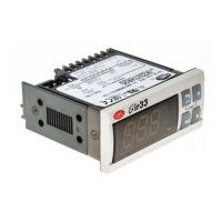
2. POWERCOMPACT SMALL
2.1 Dimensions
Appearance and ergonomics:
Key:
1. drilling template standard models 138.5 x 29 mm.
wide models from 138,5 x 29 mm to 150x31 mm
2.2 Electrical specifi cations
voltage power
Power supply
model S: 115 - 230 V~ 50/60 Hz; 6 VA, 50 mA~ max
Insulation guaranteed by the power supply insulation from very low voltage parts reinforced; 6 mm air, 8 mm surface; 3750 V insulation
insulation from relay outputs basic; 3 mm air, 4 mm surface; 1250 V insulation
Inputs S1 NTC or PTC, depending on the model
S2 NTC or PTC, depending on the model
DI1 voltage-free contact, contact resistance < 10 ohm, closing current 6 mA
S3 NTC or PTC, depending on the model
DI2 voltage-free contact, contact resistance < 10 ohm, closing current 6 mA
S4 NTC or PTC, depending on the model
Maximum distance between probes and digital inputs less than 10 m. Note: in the installation, keep the power supply and load connections
separate from the probe, digital inputs, repeater display and supervisor cables.
Type of probe Std. Carel NTC 10 k at 25 °C, range –50 to 90 °C
measurement error: 1 °C in the range –50 to 50 °C
3 °C in the range +50 to 90 °C
High temperature NTC 50 k at 25 °C, range –40 to 150 °C
measurement error: 1.5 °C in the range –20 to 115 °C
4 °C in the range outside of -20 to 115 °C
Std. Carel PTC (specifi c model) 985 at 25°C, range -50 to 150 °C
measurement error: 2 °C in the range –50 to 50 °C
4 °C in the range +50 to 150 °C
Relay outputs depending on the model
5 A EN60730-1: 250 V~ 5 (1) A; 100,000 operating cycles
UL 873: 250 V~ 5A res 1FLA 6LRA C300; 30,000 operating cycles
8 A EN60730-1: 250 V~ 8 (4) on N.O., 6 (4) on N.C., 2 (2) on N.O. and N.C.; 100,000 operating cycles
UL 873: 250 V~ 8A res 2FLA 12LRA C300; 30,000 operating cycles
30 A EN60730-1: 250 V~ 12 (10) A; 100,000 operating cycles
UL 873: 250 V~ 12A res 2HP 72LRA; 30,000 operating cycles
Relay not suitable for fl uorescent loads (neon lights, ...) that use starters (ballasts) with phase-shift capacitors. Fluorescent lamps with electro-
nic control devices or without phase-shift capacitors can be used, within the operating limits specifi ed for each type of relay.
insulation from very low voltage parts reinforced; 6 mm air, 8 mm surface; 3750 V insulation
insulation between the relay outputs basic; 3 mm air, 4 mm surface; 1250 V insulation
Connections
Type of connection Cross-sections Maximum current
fi xed screw for cables from 0.5 to 2.5 mm
2
12A
plug-in for screw blocks
fi xed screw vertical
spade with crimped contact
The correct sizing of the power and connection cables between the instrument and the loads is the responsibility of the installer.
Maximum current at terminals 4 and 7 is 12A. In the max load and max operating temp. conditions, the cables used must be suitable for ope-
ration up to 105°C.
 Loading...