38
ENG
ir33 universale +030220801 - rel. 1.0 - 16.04.2008
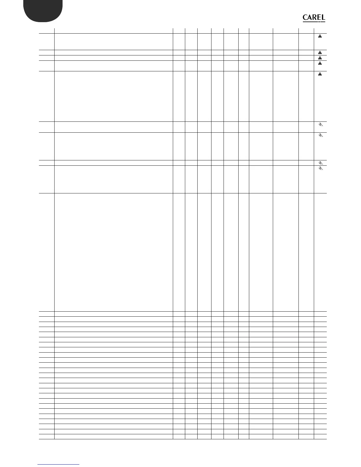
Par. Description Note Def Min Max UoM Typ. CAREL SVP ModBus® R/W Icon
P26 High temperature alarm threshold
if P29=0, P26=0 : threshold disabled
if P29=1, P26=200 : threshold disabled
150 P25 150 °C/°F A 19 20 R/W
P27 Alarm di erential 2 0 50 °C/°F A 20 21 R/W
P28 Alarm delay time 120 0 250 min I 50 123 R/W
P29 Type of alarm threshold
0=relative; 1=absolute
1 0 1 - D 165 27 R/W
c29 Digital input 1
0=Input not active
1=Immediate external alarm, automatic reset
2=Immediate external alarm, manual reset
3=Delayed external alarm(P28), manual reset
4=Control ON/OFF in relation to status of digital input
5=Start/stop operating cycle from button
Validity: c0 other than 6,7, & if c33= with “dependence”=16 &
17. With alarm, the status of the relays depends on c31
0 0 5 - I 51 124 R/W
c30 Digital input 2
See c29
0 0 5 - I 52 125 R/W
c31 Status of control outputs with alarm from digital input
0= All outputs OFF
1= All outputs ON
2= “Reverse” outputs OFF, others unchanged
3= “Direct” outputs OFF, others unchanged
0 0 3 - I 53 126 R/W
c32 Serial connection address 1 0 207 - I 54 127 R/W
c33 Special operation
0=Disabled
1= Enabled
(Before changing, make sure the desired start mode (c0) has
been selected and programmed)
0 0 1 - D 166 28 R/W
c34 Dependence of output 1
0=output not enabled
1=control output (St1,P1)
2=control output (St2,P2)
3=alarm from digital input (relay OFF)
4= alarm from digital input (relay ON)
5= serious alarms & E04 (relay OFF)
6= serious alarms & E04 (relay ON)
7= serious alarms & E05 (relay OFF)
8= serious alarms & E05 (relay ON)
9= alarm E05 (relay OFF)
10= alarm E05 (relay ON) )
11=alarm E04 (relay OFF) )
12=alarm E04 (relay ON)
13=serious alarm(relay OFF)
14= serious alarm(relay ON)
15=timer
16=control output with change set point & reverse operating
logic from digital input 1
17=control output with change set point & maintain operating
logic from digital input 1
1 0 17 - I 55 128 R/W 1
c35 Type of output 1 0 0 1 - D 167 29 R/W 1
c36 Activation of output 1 -25 -100 100 % I 56 129 R/W 1
c37 Di erential/logic of output 1 25 -100 100 % I 57 130 R/W 1
d34 Activation restriction for output 1 0 0 3 - I 58 131 R/W 1
d35 Deactivation restriction for output 1 2 0 4 - I 59 132 R/W 1
d36 Minimum value of modulating output 1(*) 0 0 100 % I 60 133 R/W 1
d37 Maximum value of modulating output 1(*) 100 0 100 % I 61 134 R/W 1
c38 Dependence of output 2 1 0 17 - I 62 135 R/W 2
c39 Type of output 2 0 0 1 - D 168 30 R/W 2
c40 Activation of output 2 -50 -100 100 % I 63 136 R/W 2
c41 Di erential/logic of output 2 25 -100 100 % I 64 137 R/W 2
d38 Activation restriction for output 2 1 0 3 - I 65 138 R/W 2
d39 Deactivation restriction for output 2 3 0 4 - I 66 139 R/W 2
d40 Minimum value of modulating output 2(*) 0 0 100 % I 67 140 R/W 2
d41 Maximum value of modulating output 2(*) 100 0 100 % I 68 141 R/W 2
c42 Dependence of output 3 1 0 17 - I 69 142 R/W 3
c43 Type of output 3 0 0 1 - D 169 31 R/W 3
c44 Activation of output 3 -75 -100 100 % I 70 143 R/W 3
c45 Di erential/logic of output 3 25 -100 100 % I 71 144 R/W 3
d42 Activation restriction for output 3 2 0 3 - I 72 145 R/W 3
d43 Deactivation restriction for output 3 4 0 4 - I 73 146 R/W 3
d44 Minimum value of modulating output 3(*) 0 0 100 % I 74 147 R/W 3
d45 Maximum value of modulating output 3(*) 100 0 100 % I 75 148 R/W 3
c46 Dependence of output 4 1 0 17 - I 76 149 R/W 4
c47 Type of output 4 0 0 1 - D 170 32 R/W 4
 Loading...


