- Min/max valori di tensione e pressione
Da /09 a /12: si imposta il valore minimo/massimo di tensione e
pressione del segnale raziometrico.
- Calibrazione sonde
Da /13 a /20: consente di calibrare il sensore relativo (da B1 a B8).
- Filtro digitale
/21: Consente di stabilire il coefficiente usato nel filtraggio digitale del
valore misurato. Valori elevati di questo parametro consentono di eliminare
eventuali disturbi continui agli ingressi analogici (ma diminuiscono la
prontezza di misura). Il valore consigliato è pari a 4 (default).
- Limitazione ingresso
/22: Consente di stabilire la massima variazione rilevabile dalle sonde
in un ciclo di programma della macchina; in pratica le variazioni massime
ammesse nella misura sono comprese tra 0,1 e 1,5 unità (bar, °C o °F
a seconda della sonda e dell’unità di misura) ogni secondo circa. Valori
bassi del parametro consentono di limitare l'effetto di disturbi di tipo
impulsivo.Valore consigliato 8 (default).
- Unità di misura
/23: Consente di selezionare la modalità di funzionamento con gradi
Centigradi o Fahrenheit. Al variare del parametro il µC
2
effettua
automaticamente la conversione dei valori letti dalle sonde di
temperatura NTC B1, B2, B3 nella nuova unità di misura mentre tutti gli
altri parametri impostati (set point, differenziale ecc.) rimangono invariati.
• Antigelo, resistenze di appoggio: parametri (A*)
- Set allarme antigelo (bassa temp. ambiente per unità Aria/Aria)
A01: Rappresenta la temperatura (set antigelo) dell’acqua all'uscita
degli evaporatori sotto la quale la macchina va in allarme antigelo;
- Min/max voltage and pressure values
From /09 to /12: sets the minimum/maximum voltage and pressure for
the ratiometric signal.
- Probe calibration
From /13 to /20: calibrates the corresponding sensor (from B1 to B8).
- Digital filter
/21: Establishes the coefficient used in the digital filtering of the value
measured. High values for this parameter will eliminate any continuous
disturbance at the analogue inputs (however decrease the promptness
of measurement). The recommended value is 4 (default).
- Input limit
/22: Establishes the maximum variation that can be measured by the
probes in one unit program cycle; in practice, the maximum variations
allowed in the measurement are between 0. 1 and 1.5 units (bars, °C
or °F, depending on the probe and the unit of measure) approximately
every one second. Low values for this parameter will limit the effect of
impulsive disturbance. Recommended value 8 (default).
- Unit of measure
/23: Selects the unit of measure as degrees centigrade or Fahrenheit.
When the parameter is modified, the µC
2
automatically converts
the values read by the NTC temperature probes B1, B2, B3 into the new
unit of measure; while all the other parameters set (set point, differential
etc. ) remain unchanged.
Antifreeze, auxiliary heater: parameters (A*)
- Antifreeze alarm set point (low ambient temp. for air/air units)
A01: This represents the temperature (antifreeze set point) of the water
at the evaporator outlet below which an antifreeze alarm is
40
µC
2
- cod. +030220420 - rel. 2.0 - 18.10.04
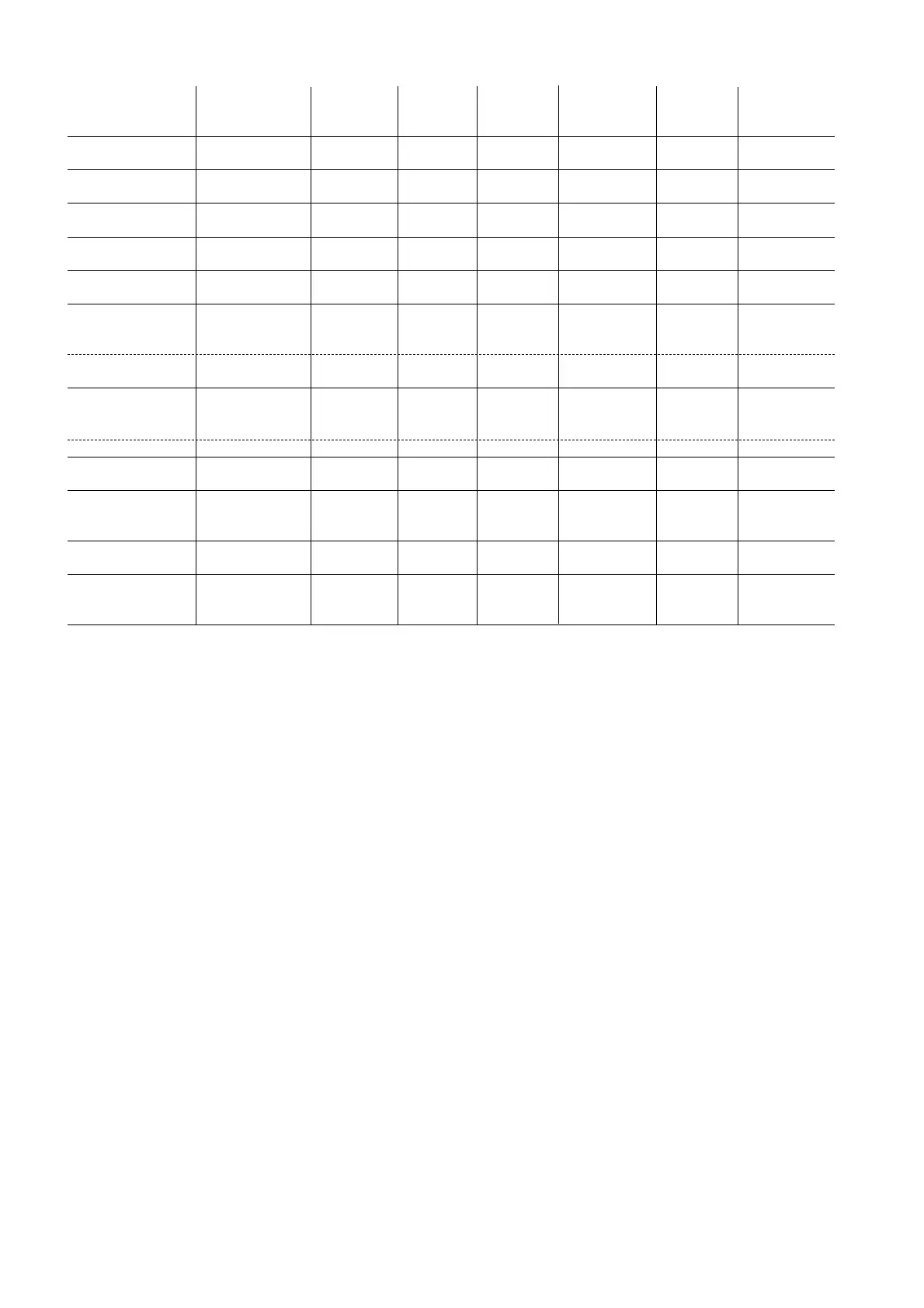
Type of unit Temp control Antifreeze Cond. temp Press. probe Antifreeze Cond. temp Press. probe
Parameter H01 probe probe probe 1st circuit probe probe 2nd circuit
1st circuit 1st circuit 2nd evaporator 2nd circuit
0= air/air B1 B2 (low outlet B3 B4 Not used B7 B8
temperature)
1= air/air heat pump B1 B2 (low outlet B3 B4 Not used B7 B8
(cooling/heating) temperature)
2= air/water Chiller B1/B2 single circuit B2 B3 B4 B6 B7 B8
(B1/B5 two circuits)
3= air/water heat pump B1/B2 single circuit B2 B3 B4 B6 B7 B8
(cooling/heating) (B1/B5 two circuits)
4= water/water Chiller B1/B2 single circuit B2 Not used Not used B6 Not used Not used
(B1/B5 two circuits)
5= water/water heat B1/B2 single circuit B2 B3 B4 B6 B7 B8
pump rev. on gas (B1/B5 two circuits)
cooling
heating B1/B2 single circuit B3 B3 B4 B7 B7 B8
(B1/B5 two circuits)
6= water/water heat B1/B2 single circuit B2 Not used B4 B6 Not used B8
pump rev. on H
2
O B1/B5 two circuits
cooling
heating B3 B2 Not used B4 B6 Not used B8
7= Air-cooled - - B3 B4 - B7 B8
condensing unit
8= Air-cooled - - B3 B4 - B7 B8
condensing unit
rev. on gas
9= Water-cooled - - B3 B4 - B7 B8
condensing unit
10= Water-cooled - B3 B3 B4 B7 B7 B8
condensing unit rev.
on gas
Tab 5.1