in condizione di allarme vengono spenti i compressori relativi al
circuito interessato, mentre la pompa rimane in attività per
diminuire la possibilità di congelamento. Il riarmo manuale
(o automatico, che dipende dal parametro P05) avviene solo quando
la temperatura dell’acqua rientra nei limiti di funzionamento
(ovvero quando supera il valore A01+A02).
Nelle macchine aria/aria (H01=0,1) il valore rappresenta la soglia
di avviso bassa temperatura ambiente; detto allarme, attivato in
funzione della sonda B1 o B2 (a seconda del parametro A06) è di
sola segnalazione e il ripristino dipende da P05.
- Differenziale allarme antigelo (bassa temperatura ambiente per
unità Aria/Aria)
A02: Determina il differenziale di intervento dell’allarme antigelo (bassa
temperatura ambiente nelle unità Aria/Aria); la condizione di
allarme non può essere annullata fino a che la temperatura non
supera il valore set + differenziale (A01+A02).
-Tempo di bypass allarme antigelo/bassa temperaura ambiente
all'accensione della macchina in modalità Inverno (riscaldamento)
A03: Determina il ritardo dell’intervento dell’allarme antigelo all’avvio
impianto. Nel caso di unità aria/aria, rappresenta il tempo di
ritardo per l’avviso di bassa temperatura ambiente (aria in
ritorno-aspirazione) solo in modalità Inverno (quando bisogna
riscaldare). Questo significa che l’ambiente da riscaldare in
Inverno è troppo freddo (soglia impostata dall’utente).
- Set attivazione resistenza antigelo/resistenze di appoggio in
raffreddamento (modalità Estate)
A04: Determina la soglia sotto la quale vengono accese le resistenze
di antigelo. Nelle unità aria/aria (H01=0, 1) rappresenta il valore di
temperatura sotto il quale si attivano le resistenze di appoggio.
Nella pompa di calore aria-aria (H01=1) le resistenze di appoggio
non vengono utilizzate in modalità Estate.
- Differenziale resistenze antigelo/resistenze di appoggio
A05: Differenziale per l'attivazione/disattivazione delle resistenze
antigelo (di appoggio nelle unità Aria/Aria).
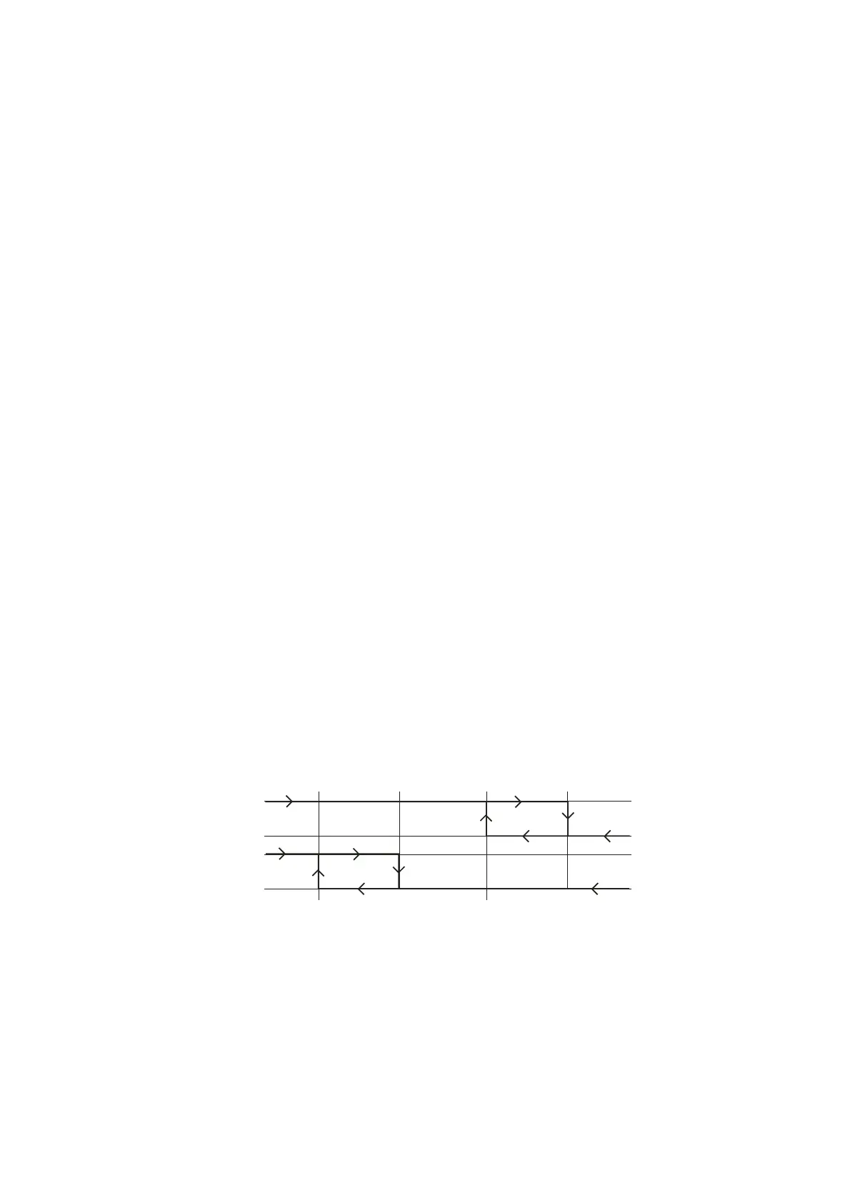
Diagramma di funzionamento dell’allarme antigelo e delle resistenze
antigelo per chiller e pompe di calore aria/acqua, acqua/acqua
- Sonda resistenze di appoggio in riscaldamento
A06: Determina la sonda da utilizzare (B1 o B2) per controllare le
resistenze di appoggio, solo per unità aria/aria (H01=0,1).
Il significato del parametro è il seguente:
A06 = 0 => Sonda di controllo vedi Tab. 5.1
A06 = 1 => Sonda antigelo vedi Tab. 5.1
Per H1=1 le resistenze in estate sono disabilitate.
Vedi Corrispondenza operativa sonde.
- Limite set allarme antigelo
A07: Stabilisce il limite minimo utilizzabile per l’impostazione del set
allarme antigelo (A01).
activated; in this condition the compressors corresponding to the
circuit in question are stopped, while the pump remains on to
decrease the possibility of freezing. The alarm is reset manually
(or automatically, depending on parameter P05) only when the
water temperature returns within the operating limits (that is,
above A01+A20).
In the Air/Air units (H1=0,1) the value represents the low room
temperature warning threshold; this alarm, activated according to
value read by probe B1 or B2 (depending on parameter A06) is
signal only, and is reset depending on the value of P05.
- Antifreeze/low room temperature (air/air) alarm differential
A02: This represents the differential for the activation of the antifreeze
alarm (low room temperature in air/air units); the alarm condition
cannot be reset until the temperature exceeds the set point +
differential (A01+A02).
- Antifreeze alarm bypass time low room temperature from unit
start in heating mode
A03: This represents the delay in the activation of the antifreeze alarm
when starting the system. In the case of air/air units, this
parameter represents the delay time for the low room temperature
(return-intake air) signal, only in heating mode. This means that
the room being heated is too cold (threshold set by the user).
- Antifreeze heater/auxiliary heater set point in cooling
A04: Determines the threshold below which the antifreeze heater is
switched on. In the air/air units (H01=0, 1) this parameter
represents the temperature value below which the auxiliary heater
is activated. In the air/air heat pumps (H01=1) the auxiliary heaters
are not used in cooling mode.
- Antifreeze heater/auxiliary heater differential
A05: Differential for the activation and deactivation of the antifreeze
heaters (auxiliary heaters in air/air units).
Operating diagram of the antifreeze alarm and the antifreeze heaters
for air/water and water/water chillers and heat pumps.
- Auxiliary heater probe in heating
A06: This determines which probe is used (B1 or B2) for control the
auxiliary heater, for air/air units only (H01=0,1). The meaning of
the parameter is the following:
A06 = 0 => Control probe see Table. 5.1
A06 = 1 => Antifreeze probe see Table. 5.1
If H1=1 the heaters are disabled in cooling mode.
See Functions of the probes.
- Antifreeze alarm set point limit
A07: Establishes the minimum limit for setting the antifreeze alarm set
point (A01).
41
µC
2
- cod. +030220420 - rel. 2.0 - 18.10.04
Antifreeze alarm differen.
Antifreeze heater differen.
Differ. allarme antigelo (A2)
Differ. resistenze antigelo (A5)
 Loading...