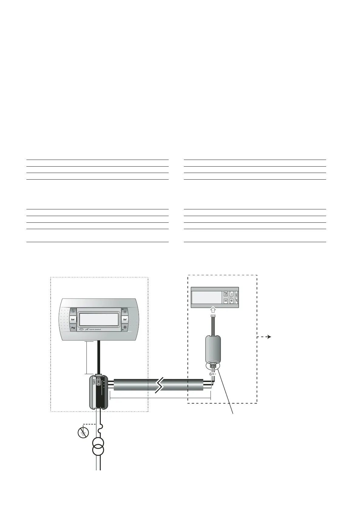
Collegamenti elettrici (Fig. 7.10.2-7.10.3)
Collegare la linea seriale RS485 in uscita dall’alimentatore “RJ12
Power supply” all’ingresso supervisore del µC
2
, utilizzando un cavo
schermato ad una coppia intrecciata. Alimentare i morsetti G-G0 con un
trasformatore e un fusibile da 250 mAT, come riportato nello schema di Fig.
7.10.2 e 7.10.3. Effettuare il collegamento tra l’alimentatore “RJ12 Power
supply” e il terminale utilizzando il cavo telefonico (cod. S90CONN002
l = 80 cm) in dotazione. Nel caso la lunghezza sia insufficiente realizzare
un cavo telefonico pin-to-pin di lunghezza massima pari a 40 m.
Avvertenze:
• utilizzare esclusivamente un trasformatore di sicurezza;
• ai fini della sicurezza è obbligatorio inserire in serie al terminale ‘G’
un fusibile da 250 mA ritardato;
• se si utilizza un trasformatore unico per µC
2
e terminale rispettare la
polarità G-G0 come da schema elettrico. L’inversione equivale ad un
cortocircuito sul secondario del trasformatore;
• non collegare a terra il secondario del trasformatore.
Linea alimentazione 24 Vac (G- G0)
Distanze tipiche Sezione minima
250 m 1,5 mm
2
(AWG16)
100 m 0,5 mm
2
(AWG20)
50 m 0,35 mm
2
(AWG22)
Tab.7.10.1
Linea seriale RS485 verso µC
2
Velocità 19200 Baud
Distanza massima RS485 1 Km (con terminazione da 120 ohm)
Caratteristiche cavo una coppia intrecciata + schermo
Sezione AWG22
Capacità per metro <90pF/m (ad esempio cavi
BELDEN 8761-8762)
Tab.7.10.2
Electrical connections (Fig. 7.10.2-7.10.3)
Connect the RS485 serial line leaving the power supply “RJ12 Power
supply” to the supervisor input on the µC
2
, using a twisted pair cable
with shield. Power terminals G-G0 from a transformer with a 250 mAT
fuse, as shown in the diagram in Fig. 7.10.2-7.10.3. Make the
connection between the power supply “RJ12 Power supply” and the
terminal using the telephone cable (code S90CONN002 l = 80 cm)
supplied. If the cable is not long enough, use a pin-to-pin telephone
cable with a maximum length of 40 m.
Warnings:
• only use safety transformers;
• for safety reasons a 250 mA slow-blow fuse must be fitted in series
with terminal ‘G’;
• if using the same transformer for the µC
2
and the terminal, respect
the polarity G-G0 as per the wiring diagram. Reversing the polarity is
the same as short-circuiting the secondary of the transformer;
• do not earth the secondary of the transformer.
24 Vac power supply line (G- G0)
Typical length Minimum cross-section
250 m 1.5 mm
2
(AWG16)
100 m 0.5 mm
2
(AWG20)
50 m 0.35 mm
2
(AWG22)
Tab.7.10.1
RS485 serial line to µC
2
Speed 19200 Baud
Maximum RS485 distance 1 km (with 120 ohm terminals)
Cable characteristics twisted pair + shield
Cross-section AWG22
Capacitance per metre < 90 pF/m (for example, BELDEN
8761-8762 cables)
Tab.7.10.2
78
µC
2
- cod. +030220420 - rel. 2.0 - 18.10.04
(see Fig. 7.10.3)
L. max.= 1000 m
L. max.= 40 m
Max. l.= 40 m
 Loading...


