Carel srl: pCO Stage Controller
page 11
C20= selection of the day with exclusion of the time band.
The parameter allows the exclusive of the time band with secondary setpoint for a selected day. The beginning time
(C21) and the ending time (C22) are programmable. The data that can be selected are the following:
0 exclusion of the time band not enabled;
1 exclusion of the time band with secondary set for the day of Monday;
2 exclusion of the time band with secondary set for the day of Tuesday;
3 exclusion of the time band with secondary set for the day of Wednesday;
4 exclusion of the time band with secondary set for the day of Thursday;
5 exclusion of the time band with secondary set for the day of Friday;
6 exclusion of the time band with secondary set for the day of Saturday;
7 exclusion of the time band with secondary set for the day of Sunday.
C21 - beginning of the time band exclusion.
The beginning time of time band exclusion with secondary set is required (see parameter C20).
C22 - end of the time band exclusion.
The ending time of the time band exclusion with secondary set is required (see parameter C20).
Caution:
do no enable at the same time the bands with reduced setpoint and the regulation of the setpoint from
analogic setpoint because both options have priority over the selected setpoint.
St3, St5 - minimum setpoint
Establish the minimum value that can be selected for the setpoint. The use of this parameter does not allow the end
to select a probe 1 setpoint lower than the value indicated by St3 and a probe 2 setpoint lower than the value
indicated by St5.
St4, St6 - maximum setpoint
Establishes the maximum value that can be selected for the setpoint. The use of this parameter does not allow the
end to select a probe 1 setpoint higher than the value indicated by St4 and a probe 2 setpoint higher than the value
indicated by St6.
St7 - secondary setpoint
Allows to select the secondary setpoint, that is valid when the time bands are enabled.
d1, d2 - device differentials
These parameters establish the values of the differentials of the devices managed by the probe 1 and 2 (inverters
excluded).
differential
setpoint
Fig. 5
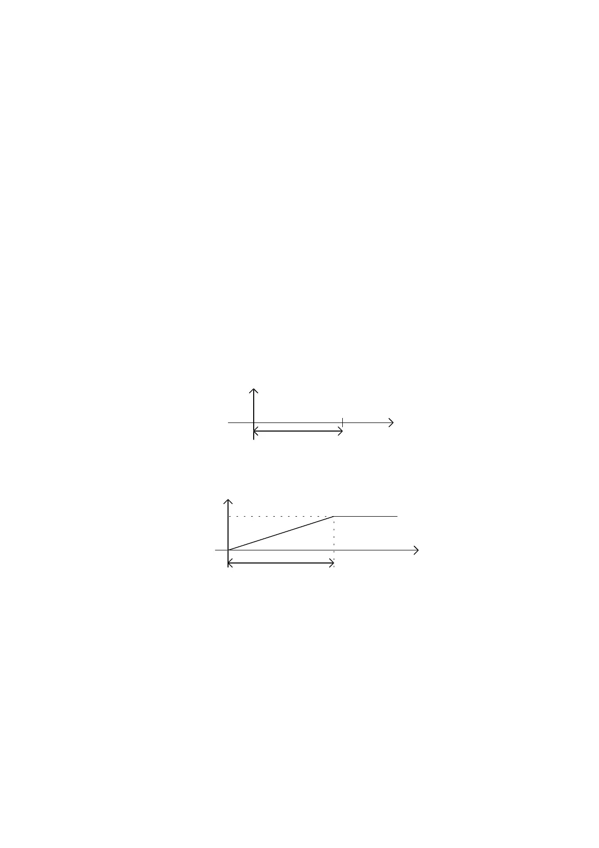
d3, d4 - inverter differentials
Differential, in addition to the active setpoint of the relevant circuit, represents the other value which can be used to
calculate the limit switch point of the inverter, i.e. the measured value to which corresponds an output of 10 volts.
setpoint
differential value measured
Volt
10
0
Fig. 6
when either d3 or d4 are involved, the differential refers to the device 1/valve inverter or to the fan inverter
respectively. These parameters are visible only if the outputs for the inverter (P20=1 and P35=1) are provided for;
furthermore, in the case of the circuit 1/valve inverter, the sideband control must be selected (P14=1).
Sr1 - inverter step of the device no.1 (see fig. 14).
The parameter is visible only when the presence of the inverter on the device no.1 has been selected, and also if
when the type of control is based on neutral zone. It establishes the increment and decrement of the device no.1
inverter (see parameter P20).
Sr2 - deviation of the device no.1 inverter (see fig. 14).
The parameter is visible only when the presence of the inverter on the device no.1 has been selected, and also
when the type of control is based on a neutral zone. It is indispensable for the calculation of the inverter insertion into
the device no.1 (see parameter P20).
Sr3 - minimum opening of the device 1/valve inverter.
The parameter is visible only when the presence of the inverter on the device no.1/valve has been selected. This
parameter makes it possible to apply a minimum voltage at the inverter/valve output. Therefore, this value is forced
when the conditions involve the application of a voltage value lower than the minimum value selected.
Sr4 - minimum aperture of the device 1/valve inverter continuously applied.

 Loading...


