Carel srl: pCO Stage Controller
page 19
CONNECTIONS
For an exhaustive description of the hardware and of the installation procedure please refer to the "User manual" of
the pCO, available on request.
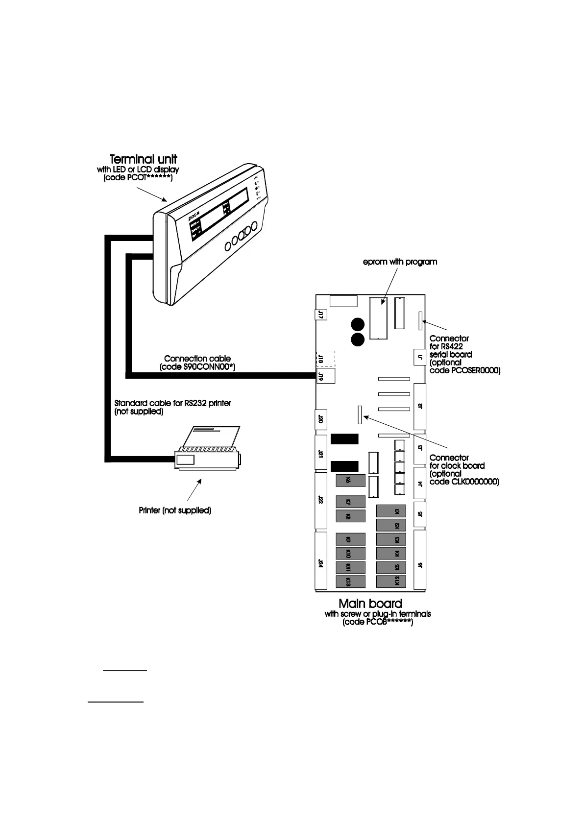
Hardware architecture
Fig. 17
The hardware architecture is as follows:
1. User TERMINAL unit with keypad, display and LEDs. The connection of the user terminal unit to the main
board is not necessary for the controller operation; it can be used for the initial programming of the main
parameters.
2. A MAIN BOARD with a unit set to be connected to the controlled devices.
3. Connection cable between the terminal unit and the main board.
4. Connection cable between the terminal unit and the serial printer (to be provided by the customer).
5. Serial printer (to be provided by the customer).

 Loading...


