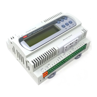
Carel srl: pCO Stage Controller
page 5
LIST OF PARAMETERS
All the bold-faced parameters are described from page 10 on
On the following tables there are two
Default
columns: on the right one there are the factory set parameters, decided
by the Carel engineerings (see on page 18). On the left one the user may write its own.
Maintenance button
Code Description Default Rating Units of
measure
t1
device 1 operating-hour display (only if device 1 is enabled) 0÷999999 h
t2
device 2 operating-hour display (only if device 2 is enabled) 0÷999999 h
t3
device 3 operating-hour display (only if device 3 is enabled) 0÷999999 h
t4
device 4 operating-hour display (only if device 4 is enabled) 0÷999999 h
t5
devices operating-hour display (only if device 5 is enabled) 0÷999999 h
t6
device 6 operating-hour display (only if device 6 is enabled) 0÷999999 h
t7
device 7 operating-hour display (only if device 6 is enabled) 0÷999999 h
t8
device 8 operating-hour display (only if device 8 is enabled) 0÷999999 h
t9
device 9 operating-hour display (only if device 9 is enabled) 0÷999999 h
t10
device 10 operating-hour display (only if device 10 is enabled) 0÷999999 h
t11
device 11 or fan-inverter operating-hour (only if fan-inverter or
device 11 is enabled)
0÷999999 h
t12
device 1/valve inverter operating-hour display (only if device
1/valve inverter is enabled)
0÷999999 h
PSt
access password to the parameters below 0 0÷999
th
device operating-hour threshold (only if there is at least one device) 0 0÷999 hx1000
r1 reset of the device 1 operating-hour number 0
0→disable 1→enable
r2 reset of the device 2 operating-hour number (only if device 2 is enabled) 0
0→disable 1→enable
r3 reset of the device 3 operating-hour number (only if device is enabled) 0
0→disable 1→enable
r4 reset of the device 4 operating-hour number (only if device 4 is enabled) 0
0→disable 1→enable
r5 reset of the device 5 operating-hour no. (only if device 5 is enabled) 0
0→disable 1→enable
r6 reset of the device 6 operating-hour no. (only if device 6 is enabled) 0
0→disable 1→enable
r7 reset of the device 7 operating-hour no. (only if device 7 is enabled) 0
0→disable 1→enable
r8 reset of the device 8 operating-hour no. (only if device 8 is enabled) 0
0→disable 1→enable
r9 reset of the device 9 operating-hour no. (only if device 9 is enabled) 0
0→disable 1→enable
r10 reset of the device 10 operating-hour no.(only if device 10 is enabled) 0
0→disable 1→enable
r11 reset of the device 11 or fan inverter operating-hour no. (only if
device 11 or fan inverter is enabled)
0
0→disable 1→enable
r12 reset of the device 1/valve inverter operating hour no. (only if
device 1/valve inverter is enabled)
0
0→disable 1→enable
n1
device 2 manual operation (only if device 1 is enabled) 0
0→disable 1→enable
n2
device 2 manual operation (only if device 2 is enabled) 0
0→disable 1→enable
n3
device 3 manual operation (only if device 3 is enabled) 0
0→disable 1→enable
n4
device 4 manual operation (only if device 4 is enabled) 0
0→disable 1→enable
n5
device 5 manual operation (only if device 5 is enabled) 0
0→disable 1→enable
n6
device 6 manual operation (only if device 6 is enabled) 0
0→disable 1→enable
n7
device 7 manual operation (only if device 7 is enabled) 0
0→disable 1→enable
n8
device 8 manual operation (only if device 8 is enabled) 0
0→disable 1→enable
n9
device 9 manual operation (only if device 9 is enabled) 0
0→disable1→enable
n10
device 10 manual operation (only if device 10 is enabled) 0
0→disable 1→enable
n11
device 11 or fan inverter manual operation (only if device 11 of
fan inverter is enabled)
0
0→disable 1→enable
n12
device 1/valve inverter manual operation (only if device 1/valve
inverter is enabled)
0
0→disable 1→enable
CL1
Probe 1 calibration (only if P21>0) 0 -5.0÷5.0 °C/F°/bar
CL2
probe 2 calibration (only if P24>0) 0 -5.0÷5.0 °C/F°/bar
CL3
probe 3 calibration (only if P22=1) 0 -5.0÷5.0 °C/F°

 Loading...