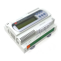
Carel srl: pCO Stage Controller
page 9
P43
identification number 1
0÷999
P44
automatic or manual reset alarms 0
0→autom. 1→manual
P45
time delay at the intervention of alarm relay 0
0÷999
min
P46
enabling OFF key 0
0→disable 1→enable
P47
serial communication baud-rate 0
0→1200 1→2400
2→4800 3→9600
4→19200
P61
circuit 1 devices switch off mode 0
0→full 1→partial
P62
cold/warm 0
0→cold 1→warm
Info button
Code Description Def
ault
Rating Unit of
measure
If1 programme version
ALARM DESCRIPTION
How to manage the
Alarms
, you have to refer to the parameter P44 at page 16
Alarm button
Code Description Effect Verify
AL 1 Exceeded threshold of the device 1 operation hours Only signalling Threshold and hour number
AL 2 Exceeded threshold of the device 2 operation hours Only signalling Threshold and hour number
AL 3 Exceeded threshold of the device 3 operation hours Only signalling Threshold and hour number
AL 4 Exceeded threshold of the device 4 operation hours Only signalling Threshold and hour number
AL 5 Exceeded threshold of the device 5 operation hours Only signalling Threshold and hour number
AL 6 Exceeded threshold of the device 6 operation hours Only signalling Threshold and hour number
AL 7 Exceeded threshold of the device 7 operation hours Only signalling Threshold and hour number
AL 8 Exceeded threshold of the device 8 operation hours Only signalling Threshold and hour number
AL 9 Exceeded threshold of the device 9 operation hours Only signalling Threshold and hour number
AL 10 Exceeded threshold of the device 10 operation hours Only signalling Threshold and hour number
AL 11 Exceeded threshold of the device 11 or fan
inveter operation
Only signalling Threshold and hour number
AL 12 Exceed. hour threshold of the device 1/valve inverter Only signalling Threshold and hour number
AL 13
Not operating Eeprom Only signalling
Reset manufacture values and turn the
pCO off.
If when turning on again AL13
remains, replace the
board
AL 14
Probe 1 is not connected or does not operate See page 15 Connections of probe 1
AL 15
Probe 2 is not connected or does not operate See page 15 Connections of probe 2
AL 16
Detection of high-pressure switch/antifreeze Device complete stop Wiring of the digital inputs 1÷10
AL 17
Detection of low-pressure/switch/flow regulator Device complete stop Wiring of the digital input 12
AL 18 Stop of the device 1 Device 1 Stop and
inverter of the device 1
Wiring of the digital input 1
AL 19 Stop of the device 2 Stop of the device 2 Wiring of the digital input 2
AL 20 Stop of the device 3 Stop of the device 3 Wiring of the digital input 3
AL 21 Stop of the device 4 Stop of the device 4 Wiring of the digital input 4
AL 22 Stop of the device 5 Stop of the device 5 Wiring of the digital input 5
AL 23 Stop of the device 6 Stop of the device 6 Wiring of the device 6
AL 24 Stop of the device 7 Stop of the device 7 Wiring of the device 7
AL 25 Stop of the device 8 Stop of the device 8 Wiring of the device 8
AL 26 Stop of the device 9 Stop of the device 9 Wiring of the device 9
AL 27 Stop of the device 10 Stop of the device 10 Wiring of device 10
AL 28 Stop of the device 11 or stop of the fan inverter Stop of the device 11 Wiring of the device 11
AL 29 Probe 1 threshold of high is exceeded Only signalling Wiring of the probe 1 and verification
of the threshold of high
AL 30 Probe 1 threshold of low is exceeded Only signalling Wiring of the probe 1 and verification
of the threshold of low
AL 31 Probe 2 threshold of high is exceeded Only signalling Wiring of the probe 2 and verification
of the threshold of high

 Loading...