Carel srl: pCO Stage Controller
page 25
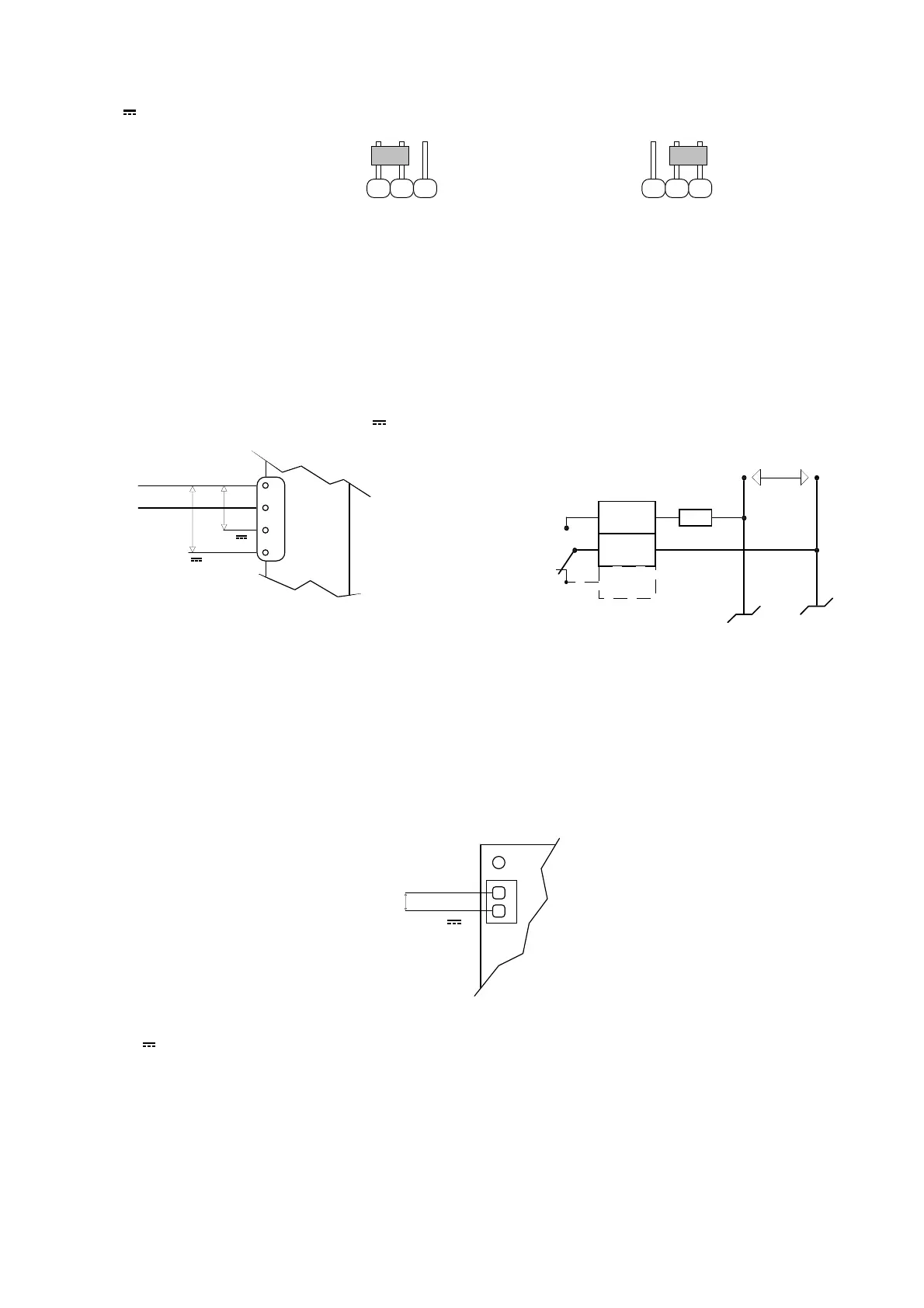
As previously mentioned the analog inputs B5 and B6 can receive either probes with voltage output signals (-1÷1
V
) or probes with current output signals (4÷20mA).
123 123
4 - 20 mA -1 / 1 Volt
(factory set)
Fig. 23
Pin-strip J14 refers to the input B5, while pin-strip J15 refers to the input B6 (see Fig. 18 page 20).
CONNECTION OF THE OUTPUTS
• 11 relay digital outputs, 8 of which with normally open contacts (NO1÷NO8) and 3 with changeover contacts
(NO9÷NO11).
• 2 optoinsulated analog outputs 0-10 V
(Y0, Y1).
Analog outputs Digital outputs
Fig. 24
The terminals used for analog output power supply (VG0 e VG1), can be connected directly to the terminals used to
supply pCO interface card (see
Fig. 30
).
The card is suitable to be installed in electric panels by fastner and screw, but its particular mechanical dimension
allows it to be used for DIN rail mounting, by means of the optional DIN rail adapters and the metallic case (optional) provided
by Carel.
Power supply
24V~ / 24V
G
G0
J17
Fig. 25
pCO can be powered by:
24 V
+10% - 15% 10W
24 V~ +10% - 15% 50/60 Hz 15 VA
IMPORTANT
: When installing the unit, use a minimum 50 VA transformer.
The transformer must power only
the pCO and not other possible devices
. If the transformer secondary is grounded, check that the same ground
cable corresponds to the cable arriving to the control and is connected to the G0 terminal.
NOn
Cn
NCn
230 - 24 V~
VG0
VG1
Y1
Y0
0 V~ (rif.)
24 V~
max 10 V
max 10 V
power supply
Fan inverter
Comp. inverter

 Loading...


