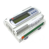
Carel srl: pCO Stage Controller
page 28
USEFUL ADVICE FOR A CORRECT INSTALLATION
Do not mount the boards in places with the following features:
• Wide and quick ambient temperature variations
• Relative humidity higher than 85%
• Strong vibrations and shocks
• Direct exposure to jets of water
• Places where explosives or flammable gaseous mixtures are present
• Exposure to dust (dust forms a corrosive patina that produced could oxidize the unit and reduce the insulation)
• Exposure to aggressive gases or pollutants such as sulphuric or ammoniacal gases, saline mists, etc., with
ensuing corrosion and/or oxidation
• High magnetic fields and/or radiofrequencies (do not place the units near transmitting antennas)
• pCO exposure to direct solar irradiation and weathering.
A wrong power supply connection can seriously damage the system:
1. Use a proper cable lug. Screw down every screw and push the cable lug through it, and then fasten the screw.
Afterwards, tighten slightly the wire to be sure it has been properly fastened.
2. Keep the cables of the probe signals and of the digital inputs as fare as possible from power cables and inductive
loads in order to avoid possible electromagnetic noises. Do not put into the same cable ducts (the ones of
the electric cables included) power cables and probe cables. Do not install the probe cables immediately
near power devices (magnetothermic contactor, etc.). Reduce as far as possible the route of the sensor cables
and avoid spiral-shaped routes that go round power devices. Use screened cables to correct the probes (min.
dia. being 0.5mm
2
).
3. Do not touch the board electronic components to avoid electrostatic charges (extremely dangerous) from the
operator to the components (see notes on page 26).
4. If the transformer secondary is grounded, check that the ground cable itself corresponds to the cable arriving to
the controller and reaching the terminal G0.
5. To mount the board inside the electrical panel use the 6 metallic mounting hardware supplied with the board
connecting them to the main electrical panel earth. Metallic mounting hardware must be fixed to the metallic
holes on the board.
6. Separate the digital-input power supply from the power supply of the pCO.
7. Do not fix the cables to the terminals of the PCOB***B** boards pushing excessively on the terminal itself thus
bending the pCO board.

 Loading...