Carel srl: pCO Stage Controller
page 22
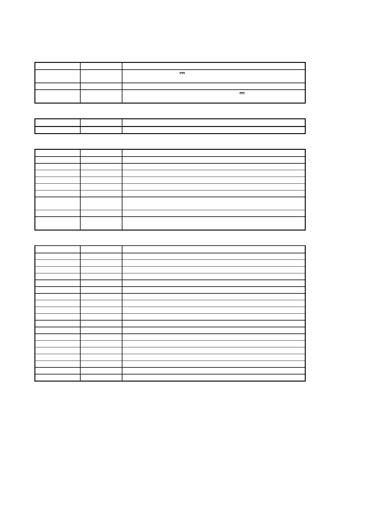
MEANING OF THE INPUTS AND OUTPUTS
Power supply
C
ONNECTOR
S
IGNAL
D
ESCRIPTION
J17 - 1 G
Power supply + 24 V
10 W or 24V~50/60 Hz 15 VA (see note on
page 25)
J17 - 2 G0 Power supply reference
J1 - 2 +24
Power supply for external active probes 24 V
(max. power that can
be supplied: 80mA
Connection with terminal unit
C
ONNECTOR
S
IGNAL
D
ESCRIPTION
J19 Terminal unit 6-way telephone cable connection with terminal unit
Analog inputs
C
ONNECTOR
S
IGNAL
D
ESCRIPTION
J2 - 1 B1 Probe 1 (only when the probe is of the NTC passive type)
J2 - 2 AVSS Common analog inputs
J2 - 3 B2 Probe 2 (only when the probe is of the NTC passive type)
J2 - 4 B3 Potentiometer for setpoint variation / Ambient air temperature (optional)
J2 - 5 AVSS Common analog inputs
J2 - 6 B4 Remote on/off (optional)
J2 - 7 B5 Probe 1 (only when the probe is of the 0-1 volt active type or is a 4-20
mA pressure probe - check pin-strip J14)
J2 - 8 AVSS Common analog inputs
J2 - 9 B6 Probe 2 (only when the probe is of the active type 0-1 volts or is a
pressure probe 4-20 mA - check pin-strip J15)
Digital inputs
C
ONNECTOR
S
IGNAL
D
ESCRIPTION
J4 - 1 ID1 Device 1 lock /Pressure switch of high pressure / antifreeze
J4 - 2 ID2 Device 2 lock / Pressure switch of high pressure / antifreeze
J4 - 3 ID3 Device 3 lock / Pressure switch of high pressure / antifreeze
J4 - 4 ID4 Device 4 lock / Pressure switch of high pressure / antifreeze
J4 - 5 ID5 Device 5 lock / Pressure switch of high pressure / antifreeze
J4 - 6 IDCM1 Digital common inputs ID1-ID5
J3 - 1 ID6 Device 6 lock / Pressure switch of high pressure / antifreeze
J3 - 2 ID7 Device 7 lock / Pressure switch of high pressure / antifreeze
J3 - 3 ID8 Device 8 lock / Pressure switch of high pressure / antifreeze
J3 - 4 ID9 Device 9 lock / Pressure switch of high pressure / antifreeze
J3 - 5 ID10 Device 10 lock / Pressure switch of high pressure / antifreeze
J3 - 6 IDCM2 Digital common inputs ID6-ID10
J21 -1 ID11-230Vac Common digital input ID11 – 230 V~ or 24 V~
J21 - 2 ID11-24Vac Fan inverter lock – 24 V~ digital input
J21 - 3 ID11 - Com Fan inverter lock – 230 V~ digital input
J21 - 4 Not connected
J21 - 5 ID12 - Com Common digital input ID12 – 230 V~ or 24 V~
J21 - 6 ID12-24 Vac Low pressure switch/flow switch – 24 V~ digital input
J21 - 7 ID12-230 Vac Low pressure switch / flow switch – 230 V~ digital input

 Loading...


