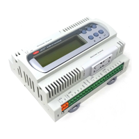
Carel srl: pCO Stage Controller
page 21
Fig. 18 references,
page 20
1. Power supply terminal 24V~50-60 Hz 15VA or 24V 10W (see note on page 25)
2. Telephone-type terminal for connective to the user terminal unit (MMI-Man Machine Interface)
3. Real-time clock board (optional)
4. RS422/RS485 optoinsulated board (optional) for connection to a serial line of supervision/telemaintenance
5. Pin strip for analog-input adopter board (eventually available upon request only)
6. EPROM with application program
7. Jumpers to select the local network communication mode
J8 in position 1-2 allows the connection of the board to a terminal unit or, possibly, to the supervisory; in position
2-3 only the connection to the local network is enabled
J9 in position 1-2 enables the supervisor to reset the pCO board, in position 2-3 makes the pCO board
independent of the reset action of the supervisor
The interface pCO boards by Carel have both jumpers in position 1-2
Caution: in this EPROM not exists the local network” management
8. Fuse 230 V~, 2A delayed
9. Digital outputs (commutable power 2300VA, 10A/230V~):
NO(n): Normally open contact output (n)
NC(n): Normally closed contact output (n)
Common contact output (n)
10. Digital inputs (24V~, 10mA)
ID(n): Digital inputs 1÷10
IDCM1: Common reference for digital inputs 1÷5
IDCM2: Common reference for digital inputs 6÷10
11. Digital inputs (230V~, 10mA)
ID11, ID12: Digital inputs 11 and 12
ID11R, ID12R: common reference for the digital inputs ID11 and ID12 respectively
12. Analog inputs
B(n): Analog input 1÷6 (8 for boards with 8 analog inputs, code PCOB000***1)
AVSS: Common reference of the analog inputs B(n)
13. Analog outputs 0÷10 V
Y(n): Analog outputs 1 and 2
VG1: External power supply for analog outputs (24V~ or 24V )
VG0: Reference for power supply and analog output signals Y0 and Y1
14. Power indicator LED
15. Analog inputs
B(n): analog inputs 7 and 8
+24 Vcc: power supply for external active probes 24V
(n) current
16. Jumper J15 to select the analog input B6 in 0÷1 V or 4÷20 mA (1-2=4÷20 mA, 2-3=0÷1 V )
17. Jumper J14 to select the analog input B5 in 0÷1 V or 4÷20 mA (1-2=4÷20 mA, 2-3=0÷1 V )
18. Jumper J28 to select the analog input B7 in 0÷1 V or 4÷20 mA (1-2=4÷20 mA, 2-3=0÷1 V )
19. Jumper J29 to select the analog input B8 in 0÷1 V or 4÷20 mA (1-2=4÷20 mA, 2-3=0÷1 V )

 Loading...