Carel srl: pCO Stage Controller
page 20
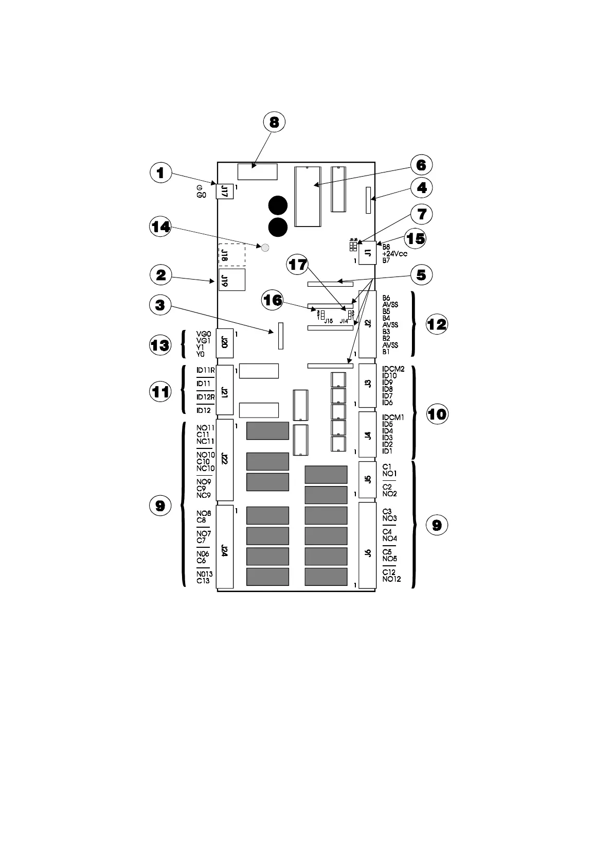
Main board - layout
Fig. 18
The main board (code PCOB000***) is the basic core of the controller and includes 4 different areas:
• microprocessor and memories of the unit
• terminal blocks necessary to interface the pCO to the controlled devices
• connectors necessary to interface pCO to the remote terminal unit, to the real-time clock board, and to the local
and supervisory network.

 Loading...


