Carel srl: pCO Stage Controller
page 31
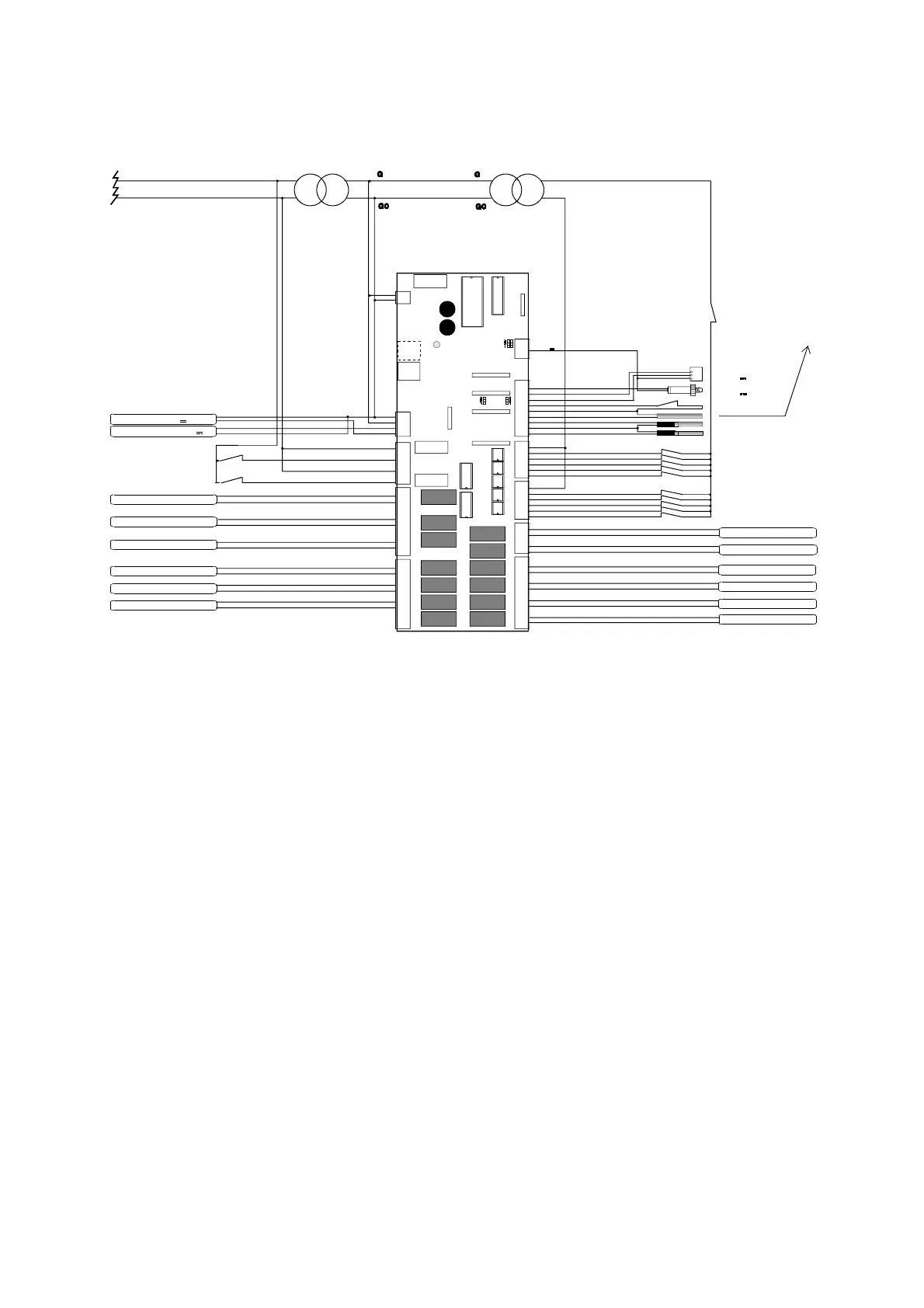
APPENDIX B: CONNECTIONS
Connection of the pCO to the other devices.
230V~ /24V~
Device 6
Generallow pre ssureswitch
(230V~ )
Rem oteon/off(opt.)
Device 11
24V~ /24V~
J
2
M
OUT
+V
J
1
8
J
1
9
J
6
J
5
J
4
J
3
J
1
J8
J9
J14J15
G
G0
1
1
1
1
1
1
1
1
1
1
1
VG 0
VG 1
Y1
Y0
ID11R
--------
ID11
--------
ID12R
--------
ID12
NO11
C11
NC11
-------
NO10
C10
NC10
-------
NO9
C9
NC9
NO8
C8
------
NO7
C7
------
N06
C6
------
N013
C13
C3
NO3
------
C4
NO4
------
C5
NO5
------
C12
NO12
C1
NO1
------
C2
NO2
IDCM 1
ID5
ID4
ID3
ID2
ID1
IDCM 2
ID10
ID9
ID8
ID7
ID6
B6
AVSS
B5
B4
AVSS
B3
B2
AVSS
B1
L
N
J
1
7
Device 11 lockor
fan inverterslock
(230V~ )
Generalalarm
Device 1 inverter (0-10V )
Fans inverter(0-10V )
(optionals)
Device 10
Device 9
Device 8
Device 7
Device 5
Device 4
Device 3
Device 2
Device 1
Device1lock
Device6lock
Device2lock
Device7lock
Device3lock
Device8lock
Device4lock
Device9lock
Device5lock
Device 10 lock
NTCCarel1 probe (opt.)
NTCCarel2 probe (opt.)
Selection setpointbypotentiom eter or
externalairtem perature
(optionals)
Generalalarm
(generalhigh pressureswitch)
Probe5(optional)
(0-1V or4-20m A)
Probe6(optional)
(0-1V or4-20m A)
J
2
0
J
2
1
J
2
4
J
2
2
+ 24V
Fig. 30
CAUTION: Separate by means of a transformer 24V~/24V~ 12VA the power supply of the digital inputs from
the power supply of the pCO board.
N.B.: IF PARTIALIZATIONS ARE USED IN CIRCUIT 1, the relative digital input must be short circuited to 24V
because they are switched off in the event that an alarm locks the relevant compressor (detected by its own digital
input).
In particular situation, partializations can be de-energized after the compressor output; if it is necessary to avoid that
delay, the user must connect the compressor alarm signal to the digital inputs used to detect the possible alarms
relative to the unlouders.
In this way the compressor and all its partializations are simultaneously switched off in the event of alarm condition.

 Loading...


