10
ENG
pRack +0300025EN rel. 1.3 - 17.12.2015
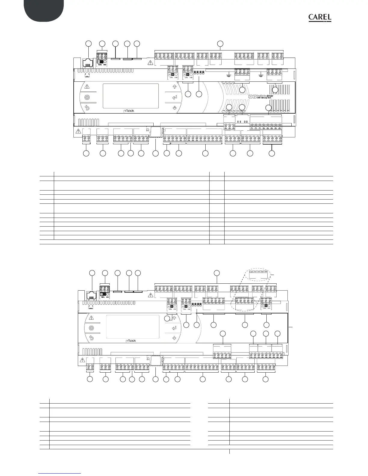
pRack pR300 D
C1
NO1
NO2
NO3
A
B
CD
C1
C4
NO4
NO5
NO6
C4
C7
NO7
C7
NO8
C8
NC8
NO12
C12
NC12
NO13
C13
NC13
C9
NO9
NO10
NO11
C9
G
G0
U1
U2
U3
GND
+VDC
+Vterm
GND
+5 VREF
U4
GND
U5
GND
VG
VG0
Y1
Y2
Y3
Y4
ID1
ID2
ID3
ID4
ID5
ID6
ID7
ID8
IDC1
U6
U7
U8
GND
ID9
ID10
ID11
ID12
IDC9
ID13H
ID13
IDC13
ID14
ID14H
J1
J24 J2 J3
J4
J5
J7
J8
J14
J10
J13J12
J16
J17
J18
J15
J6
FieldBus card BMS card
J11 pLAN
J25
BMS2
J26
FBus2
43 2 1
4
5
1
6
2 3
3
3 8
9
7
8
10
11 12
15
18
16
17
13 14
J27
1
3
2
4
J28
1
3
2
4
VBAT
G0
G
J30
GND
VREF
S1
S2
S3
S4
DI1
DI2
J29
pR300
20
21
22
24
23
Fig. 2.c
Legende:
Ref. Description Ref. Description
1 Power supply connector [G(+), G0(-)] 13 Reserved
2
+Vterm: power supply for additional terminal
+5 VREF power supply for ratiometric probes
14 Reserved
3 Universal inputs/outputs 15 Relay digital outputs
4 +VDC: power supply for active probes 16 BMS2 connector
5 Button for setting pLAN address, second display, LED 17 FieldBus2 connector
6
VG: power supply at voltage A(*) for opto-isolated analogue output
VG0: power to opto-isolated analogue output, 0 Vac/Vdc
18 Jumpers for selecting FieldBus/ BMS
7 Analogue outputs 20 Electronic valve A connector
8 ID: digital inputs for voltage A (*) 21 Electronic valve B connector
9 ID..: digital inputs for voltage A (*); IDH..: digital inputs for voltage B (**) 22 Connector for external Ultracap module (accessory)
10 pLAN telephone connector for terminal/downloading application 23 Valve driver analogue and digital inputs
11 pLAN plug-in connector 24 Valve status signal LED
12 Reserved
(*) Voltage A: 24 Vac or 28 to 36 Vdc; (**) Voltage B: 230 Vac - 50/60 Hz.
Tab. 2.b
pRack pR300 L
C1
NO1
NO2
NO3
C1
C4
NO4
NO5
NO6
C4
C7
NO7
C7
NO8
C8
NC8
NO12
C12
NC12
NO13
C13
NC13
C9
NO9
NO10
NO11
C9
G
G0
U1
U2
U3
GND
+VDC
+Vterm
GND
+5 VREF
U4
GND
U5
GND
VG
VG0
Y1
Y2
Y3
Y4
ID1
ID2
ID3
ID4
ID5
ID6
ID7
ID8
IDC1
U6
U7
U8
GND
ID9
ID10
ID11
ID12
IDC9
ID13H
ID13
IDC13
ID14
ID14H
J1
J24 J2 J3
J4 J5 J7
J8
J20
J21
J14
J10
J13
J12
J22
J16
J17
J18
J15
J6
J19
NO14
C14
NC14
NO15
C15
NC15
C16
NO16
NO17
NO18
C16
ID15H
ID15
IDC15
ID16
ID16H
Y5
Y6
ID17
ID18
IDC17
U9
GND
U10
GND
FieldBus card BMS card
J23 FBus2
J11 pLAN
J25
BMS2
J26
FBus2
43 2 1
4
5
1
6
2
3 3
3
8
9
7 8
10
11 12
15
19
15 15
9
7
3 8
13 14
N.O. Model
N.C. Model
J22
C16
NC16
NC17
NC18
C16
pR300
18
16
17
Fig. 2.d
Legende:
Ref. Description Ref. Description
1 Power supply connector [G(+), G0(-)] 11 pLAN plug-in connector
2
+Vterm: power supply for additional terminal
+5 VREF power supply for ratiometric probes
12, 13, 14 Reserved
5 Button for setting pLAN address, second display, LED 15 Relay digital outputs
6
VG: power supply at voltage A(*) for opto-isolated analogue output
VG0: power to opto-isolated analogue output, 0 Vac/Vdc
16 BMS2 connector
7 Analogue outputs 17 FieldBus2 connector
8 ID: digital inputs for voltage A (*) 18 Jumpers for selecting FieldBus/ BMS
9 ID..: digital inputs for voltage A (*); IDH..: digital inputs for voltage B (**) 19 FieldBus2 connector
10 pLAN telephone connector for terminal/downloading application
(*) Voltage A: 24 Vac or 28 to 36 Vdc; (**) Voltage B: 230 Vac - 50/60 Hz.
Tab. 2.c
 Loading...