13
ENG
pRack +0300025EN rel. 1.3 - 17.12.2015
2.2.6 Analogue outputs Y...
Type 0 to 10 V optically-isolated on Y1...Y6
Lmax 30 m
Maximum number
SMALL, MEDIUM/ BUILT-IN DRIVER 4 Y1...Y4, 0 to 10 V
LARGE 6 Y1...Y6, 0 to 10 V
Power supply external 24 Vac (+10/-15%) or 28 to 36 Vdc on VG(+), VG0(-)
Precision Y1...Y6 ± 2% full scale
Resolution 8 bit
Settling time Y1...Y6 from 1 s (slew rate 10 V/s) to 20 s (slew rate 0.5 V/s) selectable via SW
Maximum load 1 kΩ (10 mA)
Tab. 2.i
Warnings:
• for lengths > 10 m, only use shielded cable, with the shield connected to earth;
• a 0 to 10 Vdc analogue output can be connected in parallel to other outputs of the same type, or alternatively to an external source of voltage. The higher
voltage will be considered. Correct operation is not guaranteed if actuators with voltage inputs are connected;
• power the VG-VG0 analogue outputs at the same voltage on G-G0: Connect G0 to VG0 and G to VG. This is valid for both alternating and direct current
power supplies.
2.2.7 Digital outputs NO..., NC...
Type Relay. Minimum contact current: 50 mA.
Maximum no 8: SMALL; 13: MEDIUM/ BUILT-IN DRIVER; 18: LARGE;
Insulation distance
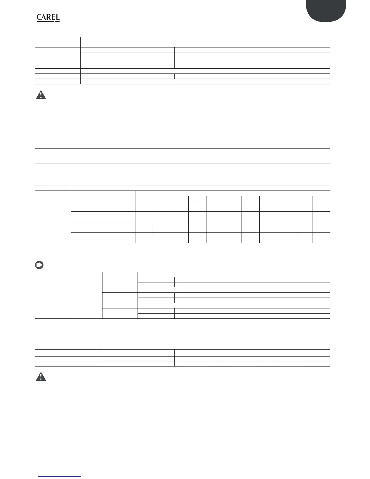
The relay outputs have diff erent features depending on the model of controller. The outputs can be divided into groups. The relays belonging
to the same group (individual cell in the table) have basic insulation and therefore must have the same voltage. Between groups (cells in the
table) there is double insulation and consequently these may have diff erent voltages. There is also double insulation between each terminal of
the digital outputs and the rest of the controller.
Relays with the same insulation
Group
Makeup of the
groups
Model 1 2 3 4567891011
SMALL 1...3 4...6 7 8 - - - ----
Type of relay Type A Type A Type A Type A - - - ----
MEDIUM/ BUILT-IN DRIVER 1...3 4...6 7 8 9...11 12 13 ----
Type of relay Type A Type A Type A Type A Type A Type A Type A ----
LARGE NO 1...3 4...6 7 8 9...11 12 13 14...15 16...18 --
Type of relay Type A Type A Type A Type A Type A Type A Type A Type A Type A --
LARGE NC 1...3 4...6 7 8 9...11 12 13 14...15 16...18 --
Type of relay Type A Type A Type A Type A Type A Type A Type A Type A Type C --
Number of
changeover
contacts
1: SMALL (relay 8)
3: MEDIUM (relay 8, 12, 13)
5: LARGE NO/NC (relay 8, 12, 13, 14 e 15)
Note: the output relays have diff erent features, depending on the model of controller.
Switchable power
Relay type A
Rated data SPDT, 2000 VA, 250 Vac, 8A resistive
Approval
UL 873 2 A 250 Vac resistive, 2A FLA, 12 LRA, 250 Vac, C300 pilot duty (30,000 cycles)
EN 60730-1 2 A resistive, 2A inductive, cosφ=0.6, 2(2)A (100,000 cycles)
Relay type B
Relay rated data SPST, 1250 VA, 250 Vac, 5A resistive
Approval
UL 873 1 A 250 Vac resistive, 1A FLA, 6 LRA, 250 Vac, C300 pilot duty (30,000 cycles)
EN 60730-1 1 A resistive, 1A inductive, cosφ=0.6, 1(1)A (100,000 cycles)
Relay type C
Relay rated data SPDT, 1250 VA, 250 Vac, 5A resistive
Approval
UL 873 1 A 250 Vac resistive, 1A FLA, 6 LRA, 250 Vac, C300 pilot duty (30,000 cycles)
EN 60730-1 1 A resistive, 1A inductive, cosφ=0.6, 1(1)A (100,000 cycles)
Tab. 2.a
2.2.8 SSR outputs (in models where featured)
Maximum number 2: SMALL (ouputs 7, 8); 2: MEDIUM (ouputs 7, 12); 6: LARGE (ouputs 7, 8, 12, 13, 14, 15)
Working voltage
24 Vac/Vdc
Load current (MAX) 1 A
Impulsive load current (MAX) 1.2 A
Tab. 2.j
Warnings:
• if the load requires higher current, use an external SSR;
• to power external resistive loads via SSRs, use the same power supply as the pRack (supplied to terminals G-G0), which must be dedicated and not shared by other
devices (contactors, coils, etc..);
• the groups that the digital outputs are divided into have two common pole terminals to simplify wiring;
• make sure that the current running through the common terminals does not exceed the rated current of an individual terminal, that is, 8 A.
 Loading...