14
ENG
pRack +0300025EN rel. 1.3 - 17.12.2015
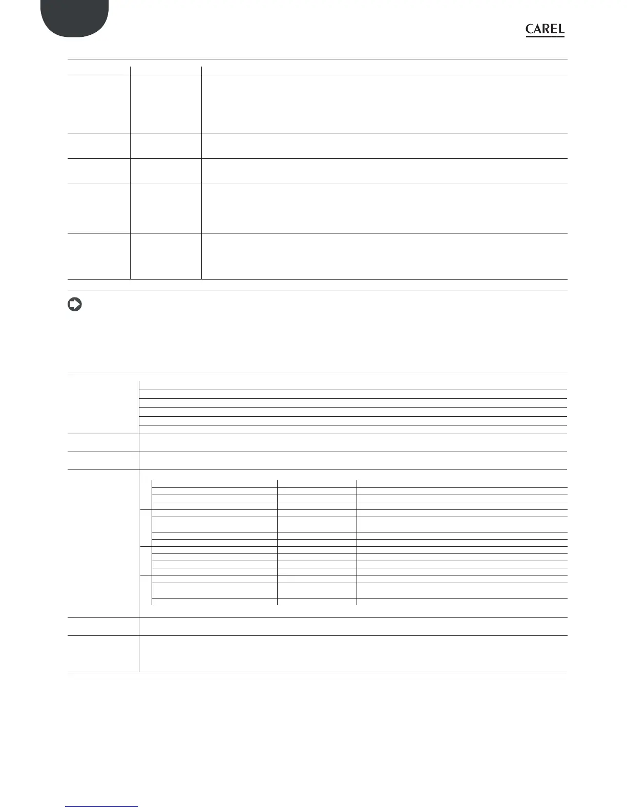
2.2.9 Serial port - Use AWG 20-22 twisted pair shielded cable for the +/-
Serial Type/connectors Features
Serial ZERO pLAN/J10, J11
• Integrated on main board
• HW driver: asynchronous half duplex RS485 pLAN
• Not optically-isolated
• Connectors: 6-pin telephone jack + 3-pin plug-in p. 5.08
• Maximum length: 500 m
• Max data rate: 115200 bit/s
• Maximum number of connectable devices: 3
Serial ONE BMS 1 Serial Card
• Not integrated on main board
• HW driver: not featured
• Can be used with all pRack family optional BMS cards
Serial TWO FieldBus 1 Serial Card
• Not integrated on main board
• HW driver: not present
• Can be used with all pRack family optional FieldBus cards
Serial THREE BMS 2 / J25
• Integrated on main board
• HW driver: asynchronous half duplex RS485 Slave
• Optically-isolated
• 3-pin plug-in connector p. 5.08
• Maximum length: 1000 m
• Max data rate: 384000 bit/s
Serial FOUR FFieldBus 2 / J26 (and
J23 on Large and
Extralarge version)
• Integrated on main board
• J23: not optically-isolated
• J26: optically-isolated
• 3-pin plug-in connector p. 5.08
• J23 and J26 are independent.
Tab. 2.k
Note: in industrial/residential environments, for distances > 10 m, shielded cable is required, with the shield connected to earth. In residential environments (EN
55014), irrespective of the cable length, on versions without valve driver, the connection cable between the controller and the terminal and the serial cable must be
shielded and connected to earth at both ends.
2.2.10 Model with electronic expansion valve driver
Valve compatibility
CAREL: E*V****
ALCO: EX4; EX5; EX6; EX7; EX8 330 Hz (recommended by CAREL); EX8 500 Hz (from ALCO specifi cations)
SPORLAN: SEI 0.5-11; SER 1.5-20; SEI 30; SEI 50; SEH 100; SEH175
Danfoss: ETS 12.5-25B; ETS 50B; ETS 100B; ETS 250; ETS 400 CCM 40, CCM 10-20-30, CCMT 2-4-8
CAREL: two CAREL EXV as for EVD EVOLUTION TWIN
SPORLAN: SER(I) G, J, K
Motor connection
Shielded 4-wire cable CAREL P/N E2VCABS*00, or AWG22 shielded 4-wire cable Lmax =10 m,
or AWG14 shielded 4-wire cable Lmax 50 m
Digital input
connection
Digital input to be activated with voltage-free contact or transistor to GND.
Closing current 5mA; maximum length < 10 m
Sonde
Maximum length 10 m or less than 30 m with shielded cable
S1 ratiometric pressure probe (0 to 5 V) resolution 0.1 % fs measurement error: 2% fs maximum; 1% typical
electronic pressure sensor (4 to 20 mA) resolution 0.5 % fs measurement error: 8% fs maximum; 7% typical
combined ratiometric pressure probe (0 to 5 V) resolution 0.1 % fs measurement error: 2 % fs maximum; 1 % typical
4 to 20 mA input (max. 24 mA) resolution 0.5 % fs measurement error: 8 % fs maximum; 7 % typical
S2 low temperature NTC 10 kΩ at 25 °C, -50T90 °C measurement error: 1°C in the range -50T50 °C; 3°C in the range +50T90 °C
high temperature NTC 50 kΩ at 25 °C,-40T150 °C measurement error: 1.5 °C in the range -20T115°C, 4 °C in range outside of
-20T115 °C
combined NTC 10 kΩ at 25 °C,-40T120 °C measurement error: 1°C in the range -40T50 °C; 3°C in the range +50T90 °C
0 to 10 V input (max 12 V) resolution 0.1 % fs measurement error: 9% fs maximum; 8% typical
S3 ratiometric pressure probe (0 to 5 V): resolution 0.1 % fs measurement error: 2% fs maximum; 1% typical
electronic pressure sensor (4 to 20 mA) resolution 0.5 % fs measurement error: 8% fs maximum; 7% typical
combined ratiometric pressure probe (0 to 5 V) resolution 0.1 % fs measurement error: 2 % fs maximum; 1 % typical
4 to 20 mA input (max. 24 mA) resolution 0.5 % fs measurement error: 8 % fs maximum; 7 % typical
S4 low temperature NTC 10 kΩ at 25 °C,-50T105 °C measurement error: 1 °C in the range -50T50 °C; 3°C in the range 50T90 °C
high temperature NTC 10 kΩ at 25 °C,-40T150 °C measurement error: 1.5 °C in the range -20T115 °C; 4 °C in range outside of
-20T115 °C
combined NTC 10 kΩ at 25 °C, -40T120 °C measurement error 1 °C in the range -40T50 °C; 3°C in the range +50T90 °C
Power to active
probes (VREF)
programmable output: +5 Vdc ±2% or 12 Vdc ±10%, Imax = 50 mA
Emergency power
supply
optional Ultracapacitor module (PCOS00UC20 or EVD0000UC0). If the controller operates constantly at temperatures near the upper limit of
60°C it’s recommended to use the external module EVD0000UC0, where possible located in the coolest point of the panel. The PCOS00UC20
and EVD0000UC0 modules can be connected at the same time to the same controller, thus doubling the energy available to close the valves.
Important: The module only powers the valve driver and not the controller.
Tab. 2.l
 Loading...