J11 pLAN
J25
BMS2
J26
FBus2
43 21
pR300
Fig. 3.n
The table below shows the reference outputs for pRack models fi tted
with SSR outputs.
Hardware version Reference relay SSR Terminal
S 7, 8 J14, J15
M, D 7, 12 J14, J17
L 7, 8, 12, 13, 14, 15 J14, J15, J17, J18, J21
Tab. 3.k
Important: the SSR relay load is powered at 24 Vac/Vdc, thus all the
other terminals in the group must be powered at 24 Vac/Vdc due to the
absence of double insulation within the group.
3.6.3 Summary table of digital outputs according to
the Versions available
Hardware
version
NO
contacts
NC
contacts
Changeover
contact
n.ro
outputs
relay in SSR
PRK300**E* Models
S 6 - - 8 2 (7, 8)
M, D 9 - 2 (8, 13) 13 2 (7, 12)
L 12 - - 18 6 (7, 12, 13, 14, 15)
PRK300**F* Models
S 7 - 1 (8) 8 -
M, D 10 - 3 (8, 12, 13) 13 -
L 13 - 5 (8, 12, 13, 14, 15) 18 -
Tab. 3.l
3.6.4 Remote connection of the digital outputs
The Sizes of the cables for the remote connection of the digital outputs
are shown in the following table:
AWG Size [mm
2
] Current [A]
20 0,5 2 A
15 1,5 6 A
14 2,5 8 A
Tab. 3.m
If the product is installed in industrial environments (application of the EN
61000-6-2 standard) the length of the connections must be less than 30
m. This length shouldn’t be exceeded in any case.
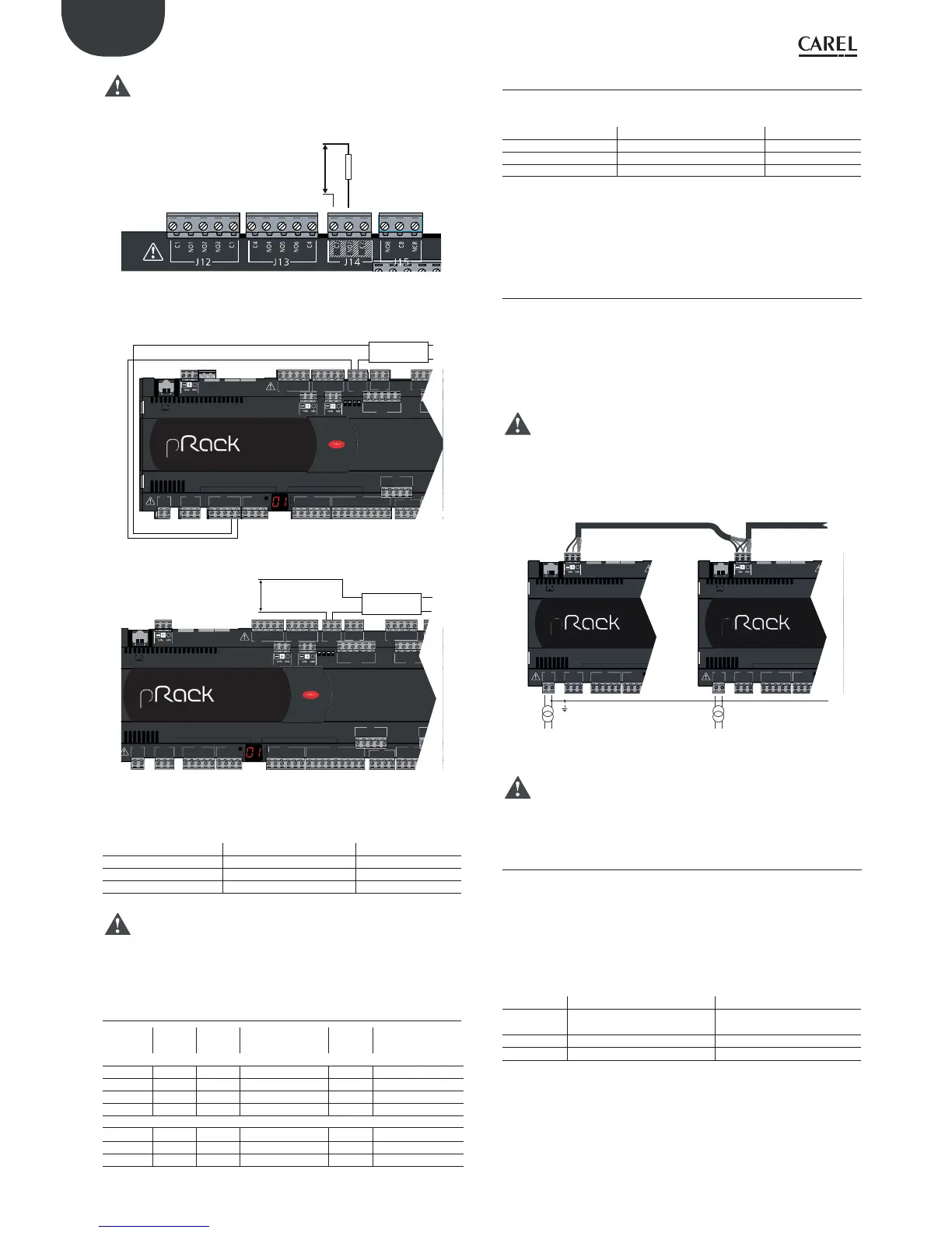
3.7 pLAN electrical connections
If the selected system confi guration involves the connection of more than
one pRack pR300 board in a pLAN, AWG20/22 twisted pair shielded cable
must be used, with capacitance between the wires less than 90 PF/m.
The maximum length of the pLAN network is 500 m with AWG22 twisted
pair shielded cable.
The boards should be connected in parallel with reference to plug-in
connector J5 (pRack Compact) or J11 (versions S, M, L).
Important: follow the network polarity: RX/TX+ on one board must
be connected to RX/TX+ on the other boards; the same applies to RX/TX-.
The fi gure shows the diagram for more than one board connected in
a pLAN network; this is a typical application with more than one board
connected inside the same electrical panel.
AWG 20/22 AWG 20/22
C1
NO1
NO2
NO3
C1
C4
NO4
NO5
NO6
C4
C7
NO7
C7
NO8
C8
NC8
NO12
C12
NC12
J11 pLAN
J25
BMS2
J26
FBus2
4 3 2 1
pR300
C1
NO1
NO2
G
G0
U1
U2
U3
GND
+VDC
+Vterm
GND
+5 VREF
U4
GND
U5
GND
VG
J1 J24 J2 J3
J10
J12
FieldBus card
J11 pLAN
pR300
Fig. 3.a
Important: pLAN connections are possible in which more than one
board is powered by diff erent transformers; for further details see
pRack system general manual: +030220335.
3.7.1 Connecting the terminals
pRack pR300 uses PGD1 terminals, either built-in or external connected
via pLAN. Up to 2 external terminals can be connected, with pLAN
addresses 31 and 32.
The connection can be made using 6-wire telephone cables (connector
J4 for Compact models or J10 for S, M, L) or shielded twisted pair cables
with 3-pin plug-in connectors (connector J5 for Compact models or J11
for S, M, L), as shown in the table
Cable type Power supply distance Power supply
6-pin phone
(J10)
10 m Taken from pRack (150 mA)
AWG24 200 m Taken from pRack (150 mA)
AWG20/22 500 m Separate, via TCONN6J000
Tab. 3.n
For further details on connecting the terminals, see the pRack system
general manual: +030220335.
 Loading...